Injection molding machine for machining of plastic products

A technology for injection molding machines and products, which is applied in the field of injection molding machines for plastic product processing, and can solve problems such as reducing injection molding precision, extruder failures, and increasing the sliding distance of check rings

Active Publication Date: 2020-10-30
NINGBO BONA MACHINERY
View PDF32 Cites 2 Cited by
  • Summary
  • Abstract
  • Description
  • Claims
  • Application Information

AI Technical Summary

Problems solved by technology

[0003] The screw heads of injection molding machines are generally tapered, which can effectively reduce the injection resistance and reduce the retention of molten material in front of the screw. However, since the plastic will decompose when heated, the inner surface of the metering chamber and the screw head will stick and burn. With the accumulation of scorched plastic, on the one hand, it will reduce the injection molding precision and reduce the quality of injection molding. On the other hand, the scorched molten material adhered to the wall of the metering chamber, as impurities, is easy to get stuck when the non-return ring moves. In the gap between the non-return ring and the metering chamber, the contact surface will be poorly contacted, which will increase the reverse fl

Method used


Image

  • Injection molding machine for machining of plastic products
  • Injection molding machine for machining of plastic products
  • Injection molding machine for machining of plastic products

Examples


Embodiment Construction

[0023] The following will clearly and completely describe the technical solutions in the embodiments of the present invention with reference to the accompanying drawings in the embodiments of the present invention. Obviously, the described embodiments are only some, not all, embodiments of the present invention. Based on the embodiments of the present invention, all other embodiments obtained by persons of ordinary skill in the art without making creative efforts belong to the protection scope of the present invention.

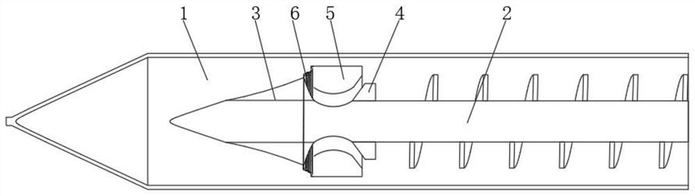
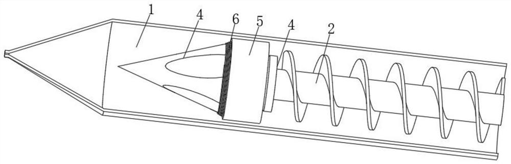
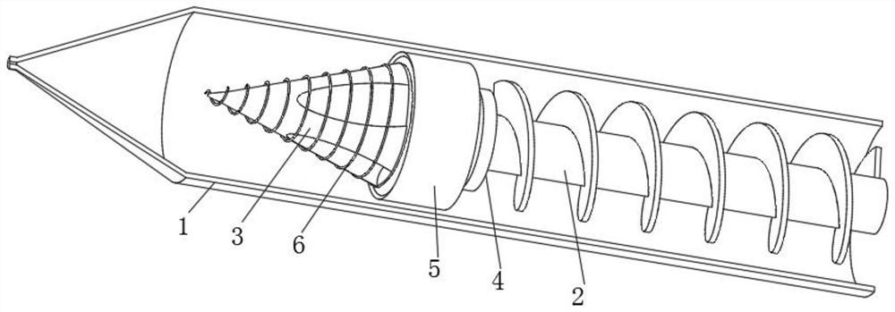
[0024] see Figure 1-3 , an injection molding machine for processing plastic products, comprising a feed bin 1, a screw rod 2, a screw head 3, a thrust ring 4 and a non-return ring 5, the thrust ring 4 and the screw head 3 are screwed to the screw rod 2, and the thread tightening direction is the same as The rotation direction of the screw 2 is the same, and the non-return ring 5 is located between the thrust ring 4 and the screw head 3. The inner wall of the...


PUM


Abstract

The invention relates to the technical field of injection molding equipment, and discloses an injection molding machine for machining of plastic products. The injection molding machine comprises a stock bin, a screw, a screw head, a thrust ring and a check ring. The thrust ring and the screw head are both in threaded connection with the screw, and the check ring is located between the thrust ringand the screw head. According to the injection molding machine for machining of the plastic products, in a low-temperature state, a spring piece can deform into a conical threaded groove with which the screw head is coated, the washing effect of a washing medium on the inner walls of the screw head and the stock bin is enhanced, impurities and scorching melt on the inner walls can be scraped off,then, under the effect of the elasticity of the spring piece, the check ring can move to the thrust ring by itself, the flow path of the melt is reduced, pre-check is achieved, at the moment when a hydraulic device is started, the contact pressure of the thrust ring and the check ring is increased, complete check can be achieved, the elasticity of the spring piece can compensate for abrasion generated by relative rotation between the screw head and the check ring, and the service life of the check ring can be effectively prolonged.

Description

technical field [0001] The invention relates to the technical field of injection molding equipment, in particular to an injection molding machine for processing plastic products. Background technique [0002] The injection molding machine consists of injection molding screw, check ring, thrust ring, screw head and hydraulic device. The screw rotates to inject the molten plastic in the silo into the front-end metering chamber of the injection molding machine, and then the hydraulic device pushes the screw horizontally to squeeze out the molten plastic. out, injected into the mold, cooled and formed. [0003] The screw heads of injection molding machines are generally tapered, which can effectively reduce the injection resistance and reduce the retention of molten material in front of the screw. However, since the plastic will decompose when heated, the inner surface of the metering chamber and the screw head will stick and burn. With the accumulation of scorched plastic, on ...

Claims


Application Information

Patent Timeline
IPC IPC(8): B29C45/47B29C45/17B29C45/60B29C45/02
CPCB29C45/02B29C45/17B29C45/1753B29C45/47B29C45/60
Inventor 不公告发明人
Owner NINGBO BONA MACHINERY
Why Eureka
Try Eureka