Electronic connector packaging equipment and packaging method

A technology for electronic connectors and packaging equipment, applied in the directions of transportation and packaging, packaging, packaging machines, etc., can solve the problems of inconsistent opening and closing of the cylinder, many control steps of the moving device, and falling electronic connectors.

Inactive Publication Date: 2020-10-30
周俊英
View PDF0 Cites 0 Cited by
  • Summary
  • Abstract
  • Description
  • Claims
  • Application Information

AI Technical Summary

Problems solved by technology

[0003] The existing technology has the following deficiencies: 1. When flipping the electronic connector, use the pneumatic gripper to grasp the electronic connector, and then drive the pneumatic gripper to rotate through the rotating device to complete the flipping process of the electronic connector; during the flipping process, the electronic connector passes through The pneumatic gripper is firmly fixed, and the pneumatic gripper is driven by compressed gas; when the compressed gas leaks or the gas is cut off, the pneumatic gripper will not be able to grasp the electronic connector tightly due to insufficient gas supply, resulting in electronic failure during the flipping process. The connector falls because it is not grasped by the pneumatic gripper, which affects the stability of the electronic connector flipping process
2. In the process of moving the electronic connector, the left and right moving mechanism and the up and down moving mechanism are used to move the whole moving device in the left and right direction and the up and down direction respectively; and the left and right moving mechanism and the up and down moving mechanism need to be respectively equipped with two drive motors As well as the driving mechanism such as the screw guide rail, two control steps are required to control the up and down movement of the moving device and control the left and right movement of the moving device during work, resulting in more control steps for the entire moving device and increasing the complexity of the device
3. In the process of moving the electronic connector, use the cylinder to clamp the electronic connector, and control the cylinder to clamp or release the electronic connector at the same time by controlling the air circuit connected to the cylinder; when moving the electronic connector, you need Clamping or loosening electronic connectors of multiple stations at the same time, due to the large number of stations and the long distance between the stations, the total length of the clamping device corresponding to the stations It is longer, and the distance between the clamping cylinder and the gas source of different stations is quite different; when the compressed gas of the gas source is transmitted to the cylinders of each station through the air circuit, at the same time, the distance between the cylinder that is closer to the gas source and the distance The air cylinders with far away gas sources have inconsistent opening and closing actions of the cylinders at different positions due to the inconsistency of the time when the compressed gas reaches the cylinders; when the moving device moves the electronic connector, the state of the cylinders at different positions clamping or loosening the electronic connector Different, thus affecting the accurate removal of electronic connectors
4. When packaging the electronic connector, use the pressing mechanism to directly press the diaphragm and the carrier tape, and connect the diaphragm and the carrier tape together through the plastic deformation between the diaphragm and the carrier tape to complete the electronic connector. packaging; and the diaphragm itself is affected by factors such as the diaphragm material, manufacturing method, and the temperature of the diaphragm’s use environment, and the plastic deformation of the diaphragm is also different when it is pressed by the pressing mechanism; when the diaphragm has high hardness and the film When the temperature of the environment where the film is used is low, the deformation of the plastic deformation of the film is small when the film is pressed by the pressing mechanism, which causes the connection between the film and the carrier tape to be weak and affects the packaging quality of the electronic connector.

Method used


Image

  • Electronic connector packaging equipment and packaging method
  • Electronic connector packaging equipment and packaging method
  • Electronic connector packaging equipment and packaging method

Examples


Embodiment 1

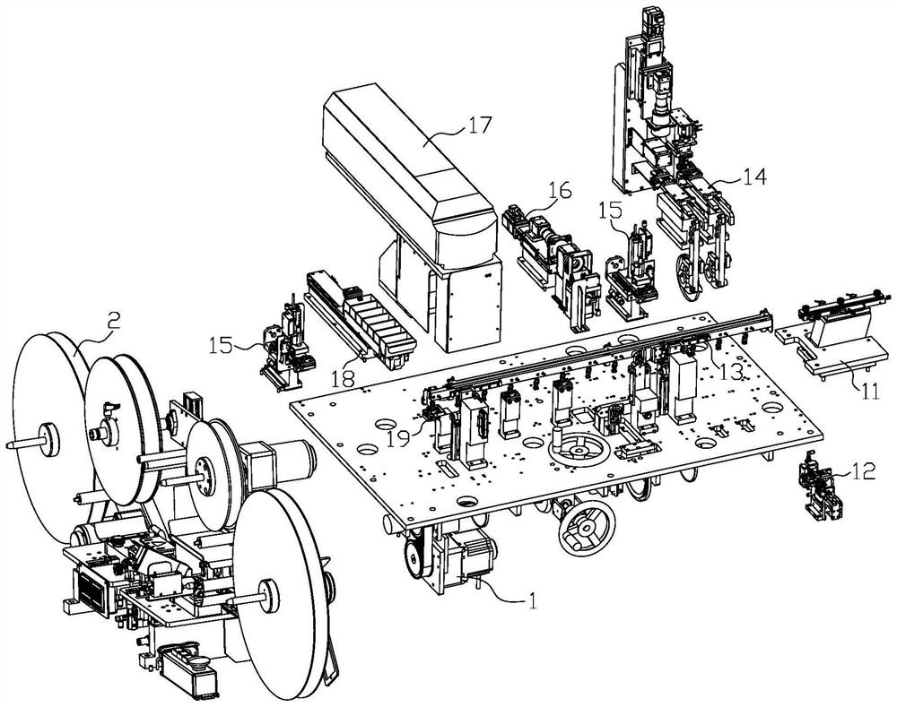
[0042] Such as figure 1 An electronic connector automatic detection and packaging production line is shown, the production line includes a frame and an electronic connector detection device 1 and an electronic connector packaging device 2 fixed on the frame; the electronic connector detection device 1 feed port and the upper The material stations are connected, and the outlet of the electronic connector testing equipment 1 is connected with the feeding port of the electronic connector packaging equipment 2; the electronic connector testing equipment 1 is used for the transportation and testing of electronic connectors; the electronic connector packaging equipment 2 is used for For automatic packaging of electronic connectors.

[0043] The electronic connector testing equipment 1 includes a working table and a feeding device 11 fixed on the working table, a connector turning device 12, a connector moving device 13, a connector performance testing device 14, a static removal dev...


PUM


Abstract

The invention relates to the field of electronic connectors. Electronic connector packaging equipment comprises a packaging rack, a carrier tape conveying device, a diaphragm conveying device, a carrier tape slideway device and carrier tape pressing devices, wherein the carrier tape conveying device, the diaphragm conveying device and the carrier tape slideway device are all fixed on the packagingrack; the carrier tape conveying device and the diaphragm conveying device are connected with the carrier tape slideway device; the number of the carrier tape pressing devices is multiple, and the plurality of carrier tape pressing devices are all fixed to the carrier tape slideway device and are connected with connector diaphragms; the carrier tape conveying device and the diaphragm conveying device are respectively used for feeding carrier tapes and the diaphragms; the carrier tape slideway device is used for conveying the carrier tapes and the diaphragms; the carrier tape pressing devicesare used for press fitting between the diaphragms and the carrier tapes; and according to the equipment, by arranging the carrier tape pressing devices, firm connection between the diaphragms and thecarrier tapes is guaranteed, and the packaging quality of an electronic connector is improved.

Description

technical field [0001] The invention relates to the field of electronic connectors, in particular to electronic connector packaging equipment, a packaging method and an automatic detection packaging production line. Background technique [0002] Electronic connectors are also often referred to as circuit connectors, electrical connectors, and bridges two conductors on a circuit so that current or signals can flow from one conductor to another conductor. The electronic connector consists of a seat body, a contact piece and a base: the lower end of the conductive contact piece is inserted into the base, and the end of the contact piece extends out of the base; the upper end of the contact piece matches the corresponding hole on the seat body, and the lower end of the seat body is fitted and fixed on the in the corresponding groove of the base. The packaged electronic connector product is composed of carrier tape, electronic connector and diaphragm: the electronic connector is...

Claims


Application Information

Patent Timeline
Patent Type & Authority Applications(China)
IPC IPC(8): B65B57/14B65B57/00B65B63/00B65B35/36B65B35/56B65B15/04B65B51/10B65B65/00
CPCB65B15/04B65B35/36B65B35/56B65B51/10B65B57/00B65B57/14B65B63/005B65B65/003
Inventor 周俊英冯道会高河叶
Owner 周俊英
Why Eureka
Try Eureka