Eureka AIR delivers breakthrough ideas for toughest innovation challenges, trusted by R&D personnel around the world.

Special lifting frame for heating plate for wood heat treatment

A wood heat treatment and heating plate technology, applied in the field of special hangers, can solve problems such as difficult operation, inability of suction cups to close the heating plate tightly, hidden dangers, etc.

Pending Publication Date: 2020-10-30
辽宁傲时木业机械有限公司
View PDF0 Cites 0 Cited by
  • Summary
  • Abstract
  • Description
  • Claims
  • Application Information

AI Technical Summary

Problems solved by technology

In the prior art, there are mainly two kinds of hangers for heating plates used for wood heat treatment. One is to hang several independent hooks under the rectangular hanging frame. When hoisting, workers need to manually hang each hook on the heating plate. Since the hook is fixed under the hanging frame in a free hanging manner, only when the heating plate is pressed against the hook by its own weight can the hook and the heating plate be hooked firmly. On the heating plate, the operation is difficult and consumes human resources; the other is to install multiple negative pressure suction cups under the rectangular hanging frame, and use the suction cups to adsorb the heating plate under the hanging frame to realize the hoisting of the heating plate. However, When the heating plate is in contact with wood, a small amount of sawdust or grease will remain on the surface, resulting in the suction cup not being able to be tightly attached to the heating plate, and the suction cup is prone to fall off during the hoisting process, posing a greater safety hazard

Method used


Image

  • Special lifting frame for heating plate for wood heat treatment
  • Special lifting frame for heating plate for wood heat treatment
  • Special lifting frame for heating plate for wood heat treatment

Examples


Embodiment Construction

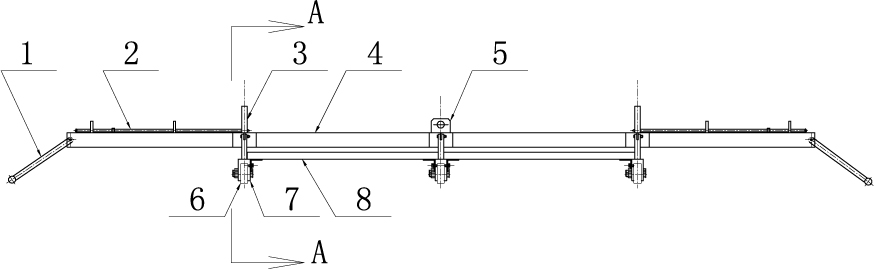
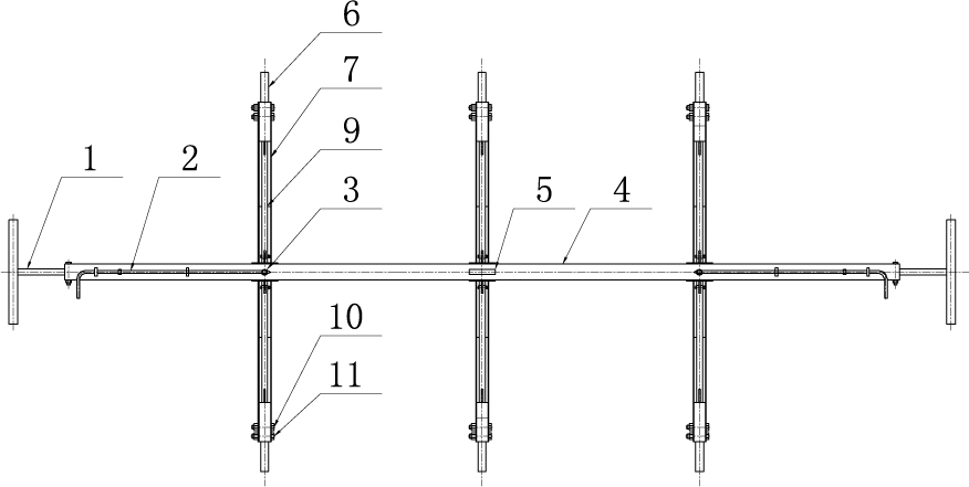
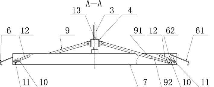
[0018] Such as figure 1 , figure 2 , image 3 As shown, the special hanger for the heating plate of the wood heat treatment of the present invention comprises at least two crossbeams 7, and a longitudinal suspension beam 4 that can be vertically lifted on the crossbeam is provided above the center of the crossbeam length direction, and a vertical suspension beam 4 is arranged on the longitudinal suspension beam. A hook frame 5 is arranged, and an operating handrail 1 is provided at both ends of the longitudinal suspension beam. A vertical guide column 3 is provided at the center of the upper surface of the beam, a vertical guide hole matched with the vertical guide column is provided on the longitudinal beam, and a vertical guide hole is provided on the longitudinal beam to prevent the vertical beam from sliding upward along the vertical guide column. The guide column lock pin 2 is provided with a guide column limit lock hole 13 matched with the lock pin on the guide column...


PUM


Abstract

The invention discloses a special lifting frame for a heating plate for wood heat treatment. The special lifting frame comprises at least two cross beams and a vertical lifting beam, and a hook frameis arranged on the vertical lifting beam; vertical guide posts are arranged on the cross beams, and a vertical guide hole is formed in the vertical lifting beam; a guide post lock pin is further arranged on the vertical beam, and guide post limiting keyholes are formed in the guide posts; the two ends of each cross beam are each provided with a heating plate hook, and the heating plate hooks are swing hooks controlled to open and close relatively to the lifting action of the cross beams from the vertical lifting beam; each swing hook is composed of a control swing arm and a hook welded at theupper end of the control swing arm, and a linkage pull rod is arranged between the vertical lifting beam and the control swing arms; and one end of the linkage pull rod is hinged on the vertical lifting beam, and the other end of the linkage pull rod is hinged at the lower end of the control swing arm. According to the special lifting frame, in the working process, pick and place of the heating plate are achieved through synchronous action of the heating plate hooks, and the special lifting frame has the advantages of the simple structure, convenient operation, time and labor saving, safety, reliability, etc.

Description

technical field [0001] The invention relates to a hoisting tool, in particular to a special hanger used for hoisting a heating plate for wood heat treatment. Background technique [0002] When wood is dried or carbonized by lamination, it is necessary to use a heating plate for wood heat treatment to heat the wood. The heating plate for wood heat treatment is mostly made of interlayer metal plates. When heating, a high-temperature working medium is introduced into the interlayer. The high-temperature working fluid cycle heats the wood. This kind of heating plate for wood heat treatment needs to be stacked alternately with wood layers when in use. Since the length of the heating plate for wood heat treatment should reach 2-8 meters, and the thickness should not exceed 0.02 meters, in order to avoid the heating plate If it is bent, deformed or damaged during placement, a special hanger is required for hoisting, so that the heating plate remains straight during the hoisting pr...

Claims


Application Information

Patent Timeline
Patent Type & Authority Applications(China)
IPC IPC(8): B66C1/28B66C15/00
CPCB66C1/28B66C15/00
Inventor 曹明军
Owner 辽宁傲时木业机械有限公司
Why Eureka
Eureka Blog
Learn More