Mechanical device supporting and maintenance device

A technology for overhauling devices and mechanical equipment, which is applied in the direction of mechanical equipment, lifting devices, lifting frames, etc., and can solve problems such as large safety hazards and heavy damage to fixed frames due to gravity

Inactive Publication Date: 2020-10-30
鲁仲斐
View PDF0 Cites 3 Cited by
  • Summary
  • Abstract
  • Description
  • Claims
  • Application Information

AI Technical Summary

Problems solved by technology

[0003] When the existing mechanical equipment is overhauled, in order to facilitate its maintenance, it is generally placed directly in the air, but as the weight of the mechanical equipment increases, the gravity damage caused to the fixed frame is greater. With the increase of th...

Method used


Image

  • Mechanical device supporting and maintenance device
  • Mechanical device supporting and maintenance device
  • Mechanical device supporting and maintenance device

Examples


Embodiment 1

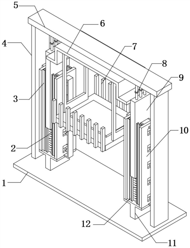
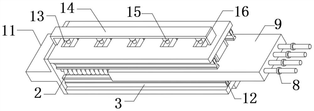
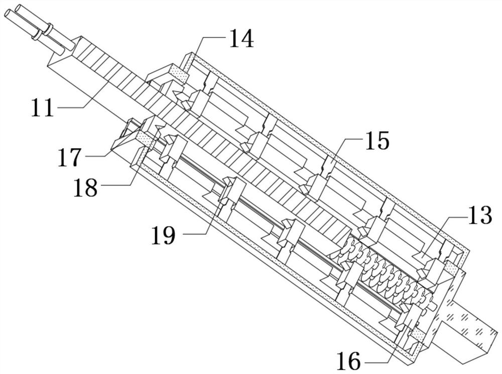
[0026] refer to Figure 1-4 , a support maintenance device for mechanical equipment, comprising a bottom plate 1, two support seats 11 are fixedly connected to the top outer wall of the bottom plate 1, and both ends of the top outer walls of the two support seats 11 are fixedly connected with adjustment plates 10, located on the same support The opposite side outer walls of the two adjusting plates 10 on the seat 11 are all fixedly connected with a connecting frame 14, and the outer walls of the two adjusting plates 10 are equidistantly provided with through holes 13, and the outer walls of the two adjusting plates 10 are close to the through holes 13. A hydraulic cylinder 15 is fixedly connected, and the other end of each hydraulic cylinder 15 is fixedly connected with an ejector block 16, and the top outer wall of the ejector block 16 is fixedly connected with a sawtooth block 19, and the top outer walls of the two support seats 11 are fixedly connected at equal distances. T...

Embodiment 2

[0035] refer to Figure 5 , a support maintenance device for mechanical equipment, comprising a bottom plate 1, two support seats 11 are fixedly connected to the top outer wall of the bottom plate 1, and both ends of the top outer walls of the two support seats 11 are fixedly connected with adjustment plates 10, located on the same support The opposite side outer walls of the two adjusting plates 10 on the seat 11 are all fixedly connected with a connecting frame 14, and the outer walls of the two adjusting plates 10 are equidistantly provided with through holes 13, and the outer walls of the two adjusting plates 10 are close to the through holes 13. A hydraulic cylinder 15 is fixedly connected, and the other end of each hydraulic cylinder 15 is fixedly connected with an ejector block 16, and the top outer wall of the ejector block 16 is fixedly connected with a sawtooth block 19, and the top outer walls of the two support seats 11 are fixedly connected at equal distances. The...


PUM


Abstract

The invention belongs to the technical field of mechanical maintenance, and particularly relates to a mechanical device supporting and maintenance device. The device aims to solve the problems that when maintained, existing mechanical equipment is always directly suspended to be conveniently maintained, but with increase of the weight of the mechanical equipment, the gravity damage to a fixing frame of the mechanical equipment is larger, meanwhile, the mechanical equipment is suspended, the gravitational potential energy of the mechanical equipment for descending is larger with increase of theweight, and potential safety hazards are larger. The device comprises a bottom plate, and the outer wall of the top of the bottom plate is fixedly connected with two supporting seats. By arranging ahydraulic cylinder, ejecting blocks, connecting blocks and a pressure reducing plate, the height of a placing plate is adjusted according to the weight of the mechanical equipment when the mechanicalequipment is maintained, so that the gravitational potential energy of the mechanical equipment is reduced; due to the ejecting blocks distributed in layers, the connecting blocks on the pressure reducing plate are limited, so that the height of the pressure reducing plate is adjusted, then the height of the placing plate is adjusted, and the potential safety hazards are reduced.

Description

technical field [0001] The invention relates to the technical field of mechanical maintenance, in particular to a support maintenance device for mechanical equipment. Background technique [0002] There are many types of mechanical equipment. When the mechanical equipment is running, some of its parts and even itself can perform different forms of mechanical movement; the mechanical equipment consists of a driving device, a transmission device, a transmission device, a working device, a braking device, a protective device, a lubrication system, and a cooling system. System and other parts, the mechanical equipment needs to be regularly inspected and repaired during use, therefore, a support inspection device is required. [0003] When the existing mechanical equipment is overhauled, in order to facilitate its maintenance, it is generally placed directly in the air, but as the weight of the mechanical equipment increases, the gravity damage caused to the fixed frame is greate...

Claims


Application Information

Patent Timeline
IPC IPC(8): B66F7/16B66F7/28F16F15/067
CPCB66F7/16B66F7/28F16F15/067
Inventor 鲁仲斐胡嘉侃
Owner 鲁仲斐
Why Eureka
Try Eureka