Rapid inversion method and device for carbon dioxide drive reservoir gas channeling channel

A technology of carbon dioxide and gas channeling, which is applied in earthwork drilling, wellbore/well components, mining fluids, etc. It can solve the problem of gas channeling in mines where a quantitative relationship cannot be established, it cannot be directly applied to mines, and it is not enough to support carbon dioxide flooding Quantification of gas channeling in reservoirs and other issues

Active Publication Date: 2020-10-30
CHINA PETROLEUM & CHEM CORP +1
View PDF4 Cites 6 Cited by
  • Summary
  • Abstract
  • Description
  • Claims
  • Application Information

AI Technical Summary

Problems solved by technology

The disadvantage of this scheme is: the established indoor model is too ideal, and cannot establish a quantitative relationship with the actual gas channeling situation in the mine, and cannot be directly applied to the mine
The disadvantage of this scheme is: when designing the model, multiple similarity criteria cannot be satisfied in the same model at the same time, so it can only focus on local fluid for similar simulation; it focuses on similar design for the flow of fluid in the cave part, ignoring the flow of the fracture part; The process of making the model is complicated and the cost is high; the model cannot be promoted in the mine and can only be used for research
The disadvantages of this scheme are: the mechanism of carbon dioxide gas channeling is theoretically analyzed on the basis of laboratory tests, and quantitative reference materials cannot be provided for the mine; The main controlling factors of gas channeling, its research content and results are not enough to support the quantification of gas channeling channels in CO2 flooding reservoirs

Method used


Image

  • Rapid inversion method and device for carbon dioxide drive reservoir gas channeling channel
  • Rapid inversion method and device for carbon dioxide drive reservoir gas channeling channel
  • Rapid inversion method and device for carbon dioxide drive reservoir gas channeling channel

Examples


Embodiment Construction

[0090] Preferred embodiments of the present application will be described in more detail below with reference to the accompanying drawings. Although preferred embodiments of the present application are shown in the drawings, it should be understood that the present application may be embodied in various forms and should not be limited to the embodiments set forth herein. Rather, these embodiments are provided so that this application will be thorough and complete, and will fully convey the scope of this application to those skilled in the art.

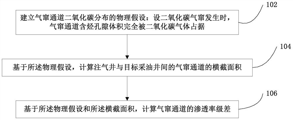
[0091] See figure 1 . figure 1 A flow chart of a fast inversion method for gas channeling in a carbon dioxide flooding reservoir according to an embodiment of the present application is shown. The method includes the following steps 102 , 104 and 106 .

[0092] Step 102, establishing a physical assumption of carbon dioxide distribution in the gas channel: assume that when carbon dioxide gas channeling occurs, the hydrocarbon-contain...


PUM


Abstract

The invention discloses a rapid inversion method and device for a carbon dioxide drive reservoir gas channeling channel. The method comprises the following steps that a physical assumption of carbon dioxide distribution of the gas channeling channel is established, it is set that the hydrocarbon-containing pore volume of the gas channeling channel is completely occupied by carbon dioxide gas whencarbon dioxide gas channeling occurs; based on the physical assumption, the cross section area A<j> of a gas channeling channel between a gas injection well and the jth target oil production well is calculated, j belongs to 1, 2,... N, and N is the total number of the target oil production wells; and based on the physical assumption and the cross sectional area A<j>, the permeability level difference beta<kj> of the gas channeling channel is calculated, and j belongs to 1, 2,... N. According to the method, rapid inversion of the gas channeling channel can be achieved, the method has the advantages of being simple in structure and convenient to use, the problems that a conventional gas channeling channel inversion method is high in cost and long in construction period are solved, and an important crack characteristic parameter basis is provided for numerical simulation of a low permeability-tight oil carbon dioxide drive reservoir and crack channeling sealing optimization design.

Description

technical field [0001] The invention relates to the field of carbon dioxide scheme design and management in oil reservoir development, and more specifically, relates to a fast inversion method for gas channeling channels in carbon dioxide flooding reservoirs and a fast inversion device for gas channeling channels in carbon dioxide flooding reservoirs. Background technique [0002] Carbon dioxide flooding is an enhanced oil recovery technology with technical superiority and widely carried out. For high-permeability reservoirs, carbon dioxide flooding has the functions of water drainage, microscopic control and displacement, viscosity reduction, and energy enhancement; for low-permeability or tight reservoirs, carbon dioxide flooding has the effects of energy enhancement, improvement of oil displacement efficiency, and viscosity reduction. Examples of various types of oil reservoirs in China prove that carbon dioxide flooding is environmentally friendly and has significant soc...

Claims


Application Information

Patent Timeline
Patent Type & Authority Applications(China)
IPC IPC(8): E21B43/16
CPCE21B43/164
Inventor 徐婷魏漪刘海龙秦学杰蒲军
Owner CHINA PETROLEUM & CHEM CORP
Why Eureka
Try Eureka