Gas conveying equipment for metallurgical machinery

A technology for conveying equipment and gas, which is applied in mechanical equipment, gas/liquid distribution and storage, pipes/pipe joints/pipe fittings, etc. It can solve problems such as repairing worker injuries, blockage of gas conveying pipes, and difficulty in cleaning, to prevent leakage. Air, improve sealing, improve the effect of stability

Inactive Publication Date: 2020-10-30
郑书元
View PDF0 Cites 0 Cited by
  • Summary
  • Abstract
  • Description
  • Claims
  • Application Information

AI Technical Summary

Problems solved by technology

[0004] Aiming at the deficiencies in the prior art, the object of the present invention is to provide a gas conveying equipment for metallurgical machinery to solve the problem of effectively conveying the gas through the conveying pipeline when conveying the gas, and there are gaps between the conveying pipeline and the pipeline. The connection is tightly connected by the connecting buckle. During the process of conveying gas, the gas will flow out from the joint of the two pipes, causing gas leakage in the gas conveying pipeline. Since the leaked gas is high-temperature steam, it is easy to cause injury to the repairing workers and affect Production efficiency, and when the gas is transported for a long time, the inner wall of the gas delivery pipe is easy to adhere to the metallurgical residual powder and other raw materials. A large amount of powder will accumulate on the inner wall of the gas delivery pipe for a long time, which is difficult to clean up, resulting in gas transportation. The problem that the tube is blocked and affects the gas delivery efficiency

Method used


Image

  • Gas conveying equipment for metallurgical machinery
  • Gas conveying equipment for metallurgical machinery
  • Gas conveying equipment for metallurgical machinery

Examples


Embodiment 1

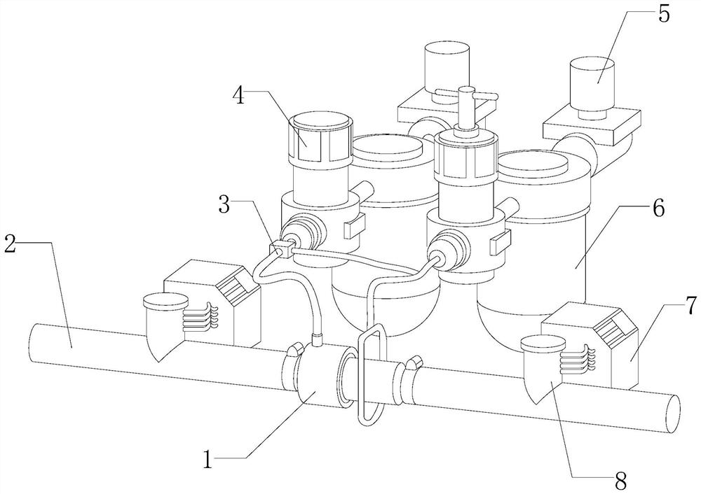
[0035] see figure 1, the present invention provides a technical solution: a gas conveying equipment for metallurgical machinery, its structure includes a processing device 1, a conveying pipe 2, a gas conveying pipe 3, an air flow chamber 4, a gas regulator 5, a gas storage chamber 6, and an outlet interface 7. Exhaust pipe 8, the processing device 1 is fitted in parallel on the conveying pipe 2, the two sides of the top of the conveying pipe 2 are provided with an exhaust pipe 8, and the exhaust pipe 8 is connected through the conveying pipe 2, the The exhaust pipe 8 communicates with the conveying pipe 2, the exhaust pipe 8 is connected with the outlet interface 7 as a whole, the outlet interface 7 is connected with the conveying pipe 2 through the exhaust pipe 8, and the outlet interface 7 is installed on On both sides of the conveying pipe 2, the top of the conveying pipe 2 is connected to the air conveying pipe 3, one end of the air conveying pipe 3 is connected inside t...

Embodiment 2

[0047] see figure 1 , the present invention provides a technical solution: a gas conveying equipment for metallurgical machinery, its structure includes a processing device 1, a conveying pipe 2, a gas conveying pipe 3, an air flow chamber 4, a gas regulator 5, a gas storage chamber 6, and an outlet interface 7. Exhaust pipe 8, the processing device 1 is fitted in parallel on the conveying pipe 2, the two sides of the top of the conveying pipe 2 are provided with an exhaust pipe 8, and the exhaust pipe 8 is connected through the conveying pipe 2, the The exhaust pipe 8 communicates with the conveying pipe 2, the exhaust pipe 8 is connected with the outlet interface 7 as a whole, the outlet interface 7 is connected with the conveying pipe 2 through the exhaust pipe 8, and the outlet interface 7 is installed on On both sides of the conveying pipe 2, the top of the conveying pipe 2 is connected to the air conveying pipe 3, one end of the air conveying pipe 3 is connected inside ...


PUM


Abstract

The invention discloses gas conveying equipment for metallurgical machinery. The equipment structurally comprises a treatment device, conveying pipes, a gas conveying pipe, a gas flow cavity, a gas regulator, a gas storage cavity, a leading-out connector and an exhaust pipe. When the equipment is in use after being improved, a guide traction part is rotated, two pull blocks are pulled inwards, a clamping rod and the conveying pipe are tightly sleeved with a sealing sleeve, the clamping rod is tightly attached between the two conveying pipes, sealing performance between the clamping rod and theconveying pipes is high, and safety and conveying efficiency of gas conveying are improved; two connecting plates are adjusted according to the thickness of the inner walls of the conveying pipes, atelescopic elastic piece generates pulling force on the two connecting plates, two attraction magnets have different magnetisms and form positive attraction, and the two connecting plates are pushed inwards, so that a wave scraper can be tightly and stably attached to the conveying pipes, powder accumulated on the inner walls of the conveying pipes can be quickly and effectively scraped, the gas can be stably conveyed, and the gas conveying efficiency is improved.

Description

technical field [0001] The invention relates to the field of metallurgical machinery, in particular to a gas delivery device for metallurgical machinery. Background technique [0002] In the metallurgical industry, it is usually necessary to use mechanical equipment such as sintering machines and rotary furnaces. These metallurgical mechanical equipment usually need to consume a large amount of gas to increase the temperature, so as to achieve the purpose of sintering and smelting. The temperature is relatively high, and the transmission pipeline needs to be installed on the metallurgical machinery, so that the high-temperature gas inside the metallurgical machinery can be stably output through the transmission pipeline. When the gas is transported, the areas that need to be improved: [0003] When the gas is transported, the gas is effectively transported through the delivery pipeline, and the delivery pipeline and the pipeline are tightly connected by the connection buckle...

Claims


Application Information

Patent Timeline
Patent Type & Authority Applications(China)
IPC IPC(8): F17D1/02F17D3/01F16L55/24
CPCF16L55/24F17D1/02F17D3/01
Inventor 郑书元
Owner 郑书元
Why Eureka
Try Eureka