
Transformer tap switch based on brake cable control

A tap changer and brake line technology, applied in transformers, variable transformers, electric switches, etc., can solve the problems of transmission delay, high production cost, and low transmission torque

Pending Publication Date: 2020-10-30
江苏金诺电气科技有限公司
View PDF1 Cites 0 Cited by
  • Summary
  • Abstract
  • Description
  • Claims
  • Application Information

AI Technical Summary

Problems solved by technology

However, the main problem of flexible shaft transmission is the transmission delay. Due to the large rotational torque of the transformer tap changer, when one end of the flexible shaft rotates through an angle, the other end hardly rotates, causing the transformer tap changer to shift gears incorrectly. The problem of the upper gear position; this kind of transmission hysteresis becomes more and more obvious with the increase of the length of the flexible shaft. For the transformer tap changer, the gear position of the operating end and the gear position of the tap changer need to correspond one by one, otherwise it cannot be realized. Effective switching of tap-changers, and the use of soft transmission, the action error of the operating end and switch end is difficult to avoid, so the flexible shaft transmission is not suitable for direct application in transformer tap-changers
In addition, the structure of the flexible shaft is relatively complex, and the transmission torque is generally not high. For transformer tap changers, in order to ensure the stability of the cooperation between the dynamic and static contacts, the dynamic and static contacts are very tight and firm, and a large force is required during switching operations. Therefore, the use of flexible shafts to drive transformer tap-changers has poor feasibility and relatively large limitations; moreover, general flexible shafts can be divided into left-handed and right-handed. , the torque that can be tolerated by reverse rotation will be smaller, and the adjustment of the transformer tap changer is a two-way adjustment, which requires adjustment in both positive and negative directions, so it is more difficult for ordinary flexible shafts to apply to the adjustment drive of the transformer tap changer; although At present, there are also flexible shafts that can bear the same torque in the tightening and loosening direction of the flexible shaft through special structural design, but the structural design of the flexible shaft is more complicated and the production cost is also higher.
If it is necessary to increase the torque of the flexible shaft, the diameter of the flexible shaft needs to be increased, which also leads to an increase in the production cost and volume of the flexible shaft, and loses the value of the long-distance transmission of the transformer tap changer
The flexible shaft also has the limitation of the turning radius. Generally speaking, the smaller the turning radius, the smaller the torque it can withstand, and the greater the torque that the flexible shaft can bear, this leads to the need to consider the turning radius when using the flexible shaft. The relationship between torque and torque prevents the flexible shaft from being bent at will. There are restrictions on the installation position of the tap changer inside the transformer and the installation position of the remote drive end or control end. If the design of the turning radius is too large, it is necessary to increase the soft shaft. The length of the shaft still has great limitations on the installation flexibility of the tap changer and the control end

Method used


Image

  • Transformer tap switch based on brake cable control
  • Transformer tap switch based on brake cable control
  • Transformer tap switch based on brake cable control

Examples


Embodiment 1

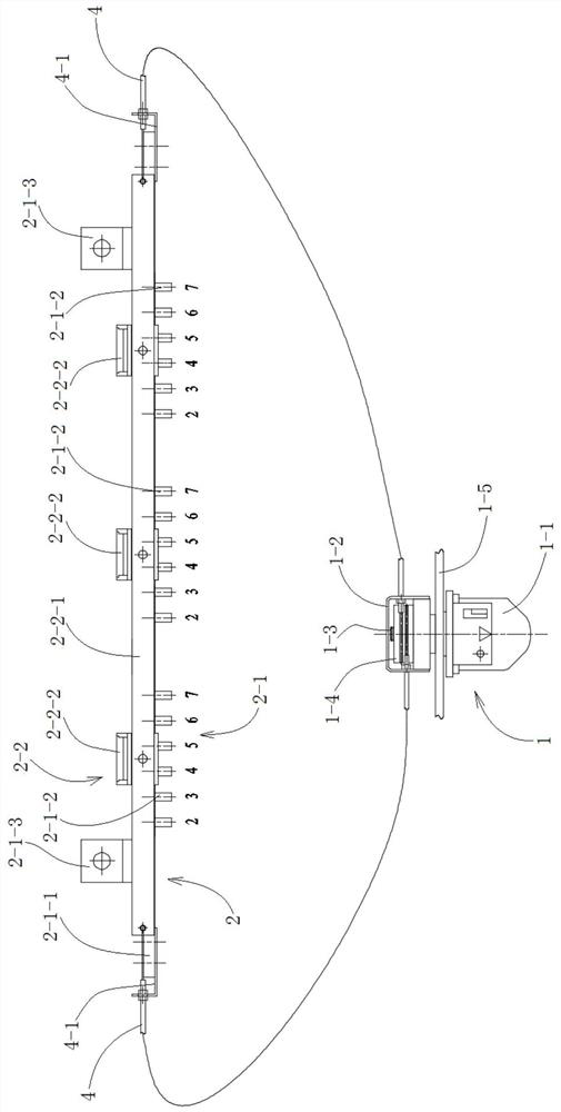
[0043] Take the transformer bar tap changer as an example. see image 3 and Figure 4 As shown, a transformer tap changer based on brake line control in this embodiment includes a remote operating mechanism 1 and a tap changer main body 2. The tap changer main body 2 includes a static contact assembly 2-1 and the above static contact assembly 2-1. The moving contact assembly 2-2 of the contact assembly 2-1 is relatively slidable and switched, which is similar to the structure of the existing tap changer. The static contact assembly 2-1 is mainly composed of the static contact bracket 2-1-1 and installed on the static Several groups of static contacts 2-1-2 are formed on the contact bracket 2-1-1, and the moving contact assembly 2-2 is mainly composed of the moving contact bracket 2-2-1 and the moving contact bracket 2-2 -1 consists of several groups of moving contacts 2-2-2, the moving contacts 2-2-2 cooperate with the static contacts 2-1-2, the static contact assembly 2-1 a...

Embodiment 2

[0048] A transformer tap-changer based on brake line control in this embodiment has the same basic structure and working principle as that of Embodiment 1, the difference is that the main body 2 of the tap-changer is also provided with a drive contact assembly 2 -2 Slide and switch the proximal control mechanism 5 that fits on the static contact assembly 2-1. Specific as Figure 5 and Figure 6As shown, a transformer tap changer based on brake line control in this embodiment includes a remote operating mechanism 1 and a tap changer main body 2. The tap changer main body 2 includes a static contact assembly 2-1 and the above static contact assembly 2-1. The contact assembly 2-1 is relatively sliding to switch the matched moving contact assembly 2-2. It should be understood that the above-mentioned "relative sliding switching" is a relative linear sliding switching for the bar tap changer, and for the cage tap changer and For the disc tap changer, it is relatively rotating and...


PUM


Abstract

The invention discloses a transformer tap switch based on brake cable control, and belongs to the field of transformer switches. The transformer tap switch comprises a far-end operating mechanism anda tap switch main body, the far-end operating mechanism and the tap switch main body are in transmission connection through a brake cable, or a near-end control mechanism is arranged on the tap switchmain body, and the far-end operating mechanism and the near-end control mechanism are in transmission connection through the brake cable; the far-end operating mechanism is in transmission connectionwith the tap switch main body through the brake cable; gear switching of the tap switches can be remotely, synchronously and one-to-one controlled by using the far-end operating mechanism. The installation positions of the far-end operating mechanism and the tap switch can be flexibly selected, so that the installation of the tap switch of the transformer is facilitated, the gear switching operation of the tap switch is facilitated, and the installation and operation of the tap switch are more flexible and convenient; and the tap switch of the transformer can be applied to various strip-shaped tap switches, cage-shaped tap switches and disc-shaped tap switches.

Description

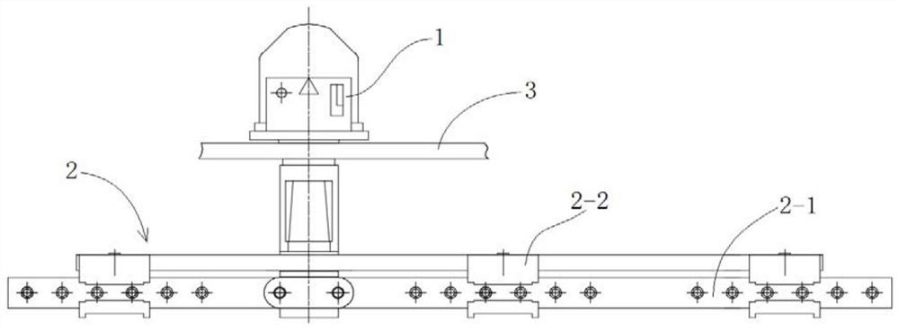
technical field [0001] The invention relates to a transformer tap changer, more specifically, to a transformer tap changer based on brake line control. Background technique [0002] The transformer tap changer is one of the indispensable main parts of the transformer by changing the connection position of the tap to change the number of turns of the high voltage coil, thereby adjusting the output voltage of the transformer. [0003] The operating mechanism of the traditional transformer tap changer and the main body of the switch are all mechanically connected as a whole. Such as figure 1 and figure 2 A bar type tap changer is shown, the main body 2 of the tap changer is mainly composed of a static contact assembly 2-1 and a moving contact assembly 2-2, and the operating mechanism 1 drives the moving contact assembly 2 through a rack and pinion mechanism -2 slide on the static contact assembly 2-1 to change the contact position of the contact. Another type of disc-shape...

Claims


Application Information

Patent Timeline
IPC IPC(8): H01H9/00H01F29/04
CPCH01F29/04H01H9/0016H01H9/0027H01H9/0044
Inventor 戴波
Owner 江苏金诺电气科技有限公司
Learn More