Mechanical self-hold electromagnetic relay

An electromagnetic relay and self-holding technology, applied in electromagnetic relays, electromagnetic relay details, relays, etc., can solve the problems affecting the reliability of relays, consume energy, increase switching costs, etc., so as to reduce labor costs and save power consumption. , the effect of reducing thermal requirements

Active Publication Date: 2020-10-30
宁波北仑聚缘贸易有限公司
View PDF11 Cites 0 Cited by
  • Summary
  • Abstract
  • Description
  • Claims
  • Application Information

AI Technical Summary

Problems solved by technology

There are some defects in this specific method: first, two buttons are required to control the on-off of the load (one for normally closed and one for normally open); secondly, the current when the electromagnetic coil is working will generate heat in the coil, and the alternating current will also generate heat at the same time. Eddy currents are generated, so the relay coil working in the holding state will generate heat accumulation and cause a large temperature rise in the coil, which seriously affects the reliability of the relay operation; in addition, the load is energized, and the electromagnetic coil is always energized to work, which consumes power and energy
[0005] The self-maintaining electromagnetic relay in this state requires two coils to work alternately, the operation process is complicated, and the power-on and power-off operations of the coil need to be controlled by pressing the switch, which increases the labor cost
The power on and off of the control circuit needs to be realized by energizing the upper and lower coils in sequence, which is complicated to operate and inconvenient to use.
One more coil increases the cost of making materials such as switches and circuits, and also increases the volume of the entire relay, which is not suitable for the control of small electrical appliances

Method used


Image

  • Mechanical self-hold electromagnetic relay
  • Mechanical self-hold electromagnetic relay
  • Mechanical self-hold electromagnetic relay

Examples


Embodiment 1

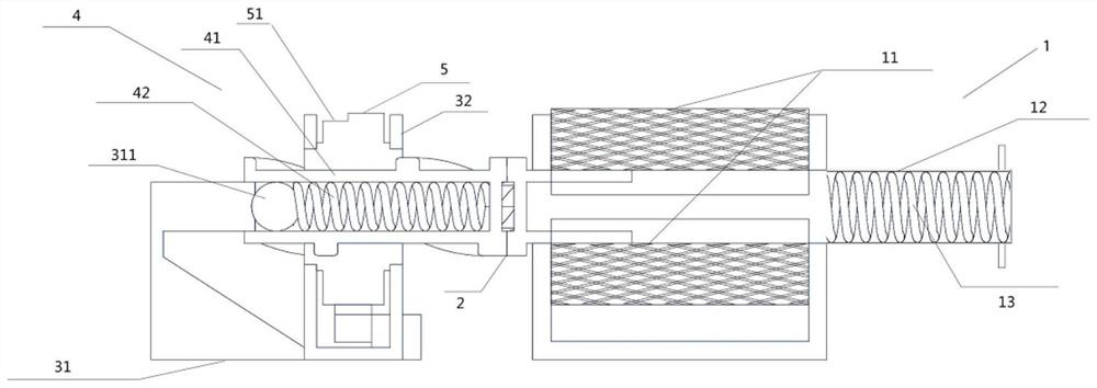
[0061] The embodiment of the present invention discloses a mechanical self-holding electromagnetic relay, such as Figure 1-3 As shown, it includes: an electromagnetic linear driver 1 with a reset function, a push head 2, a bracket 3, a drive rod 4 with a reset function, and a one-way rotating wheel 5 (the wheel 5 is provided with a ratchet and positioning ratchet), a touch switch 6 that realizes conduction through touch pressure; the electromagnetic linear drive member 1 is connected with the push head 2 to drive the push head 2 in a linear direction; one end of the push head 2 One end of the drive rod 4 is a helical tooth that cooperates with each other, and the two cooperate with each other to make the push head 2 mesh with one end of the drive rod 4 to form a one-way clutch; the other end of the drive rod 4 One end is provided with reset device 42, and described reset device 42 is connected with described bracket 3; When the push head 2 is driven, the runner 5 is driven t...

Embodiment 2

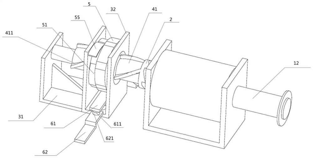
[0085] Embodiment 2 of the present invention also discloses a mechanical self-holding electromagnetic relay, such as Figure 4 As shown, the difference from Embodiment 1 is that the runner 5 and the drive rod 4, specifically, the runner 5 in Embodiment 2 is provided with a ratchet 51 and a cross 56 (the four tops of the cross 56 are convex parts 53, The remaining part is the concave portion 54, and the composition structure on the runner 5 is not limited to the cross 56, as long as there is a convex portion 53 and a concave portion 54, and the structure of the convex portion 53 and the concave portion 54 can be switched periodically), the positioning The fixed end of the ratchet 55 is connected to the bracket 3; the positioning ratchet 55 is close to the ratchet 51; the ratchet 51 is fixedly connected to the cross 56 and the central axis of the two coincides; the drive rod 4 is set There is a propelling pawl 14 close to the ratchet wheel 51 , and the runner 5 is pushed by the ...

Embodiment 3

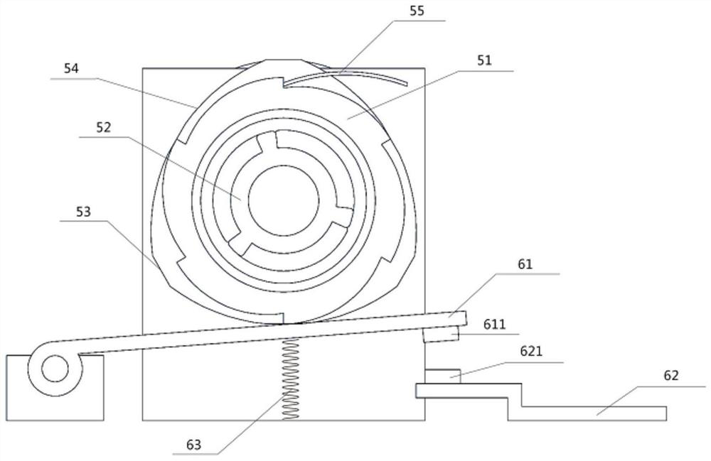
[0091] Embodiment 3 of the present invention also discloses a mechanical self-holding electromagnetic relay, such as Figure 5 As shown, the difference from Embodiments 1 and 2 is that the runner 5 and the touch switch 6, the movable end of the cross 56 is provided with a movable contact 611 (the specific movable contact piece 61 is directly cross-shaped); The touch switch 6 includes: a moving contact piece 61, a static contact piece 62, and a spring 63; wherein,

[0092] The cross 56 is the movable contact piece 61; the top of the cross 56 as the movable end is provided with a movable contact 611;

[0093] The static contact piece 62 is connected to the spring 63, so that the movable contact 611 does not contact the static contact 621 on the static contact piece 62 under the condition of not being pressed.

[0094] Thus, the cross-shaped movable contact piece 61 is embedded on the disc integrated with the ratchet 51 . The ratchet 51 rotates one tooth, the cross-shaped movab...


PUM


Abstract

The invention provides a mechanical self-hold electromagnetic relay which comprises an electromagnetic linear driving piece with a reset function, a push head, a support, a driving rod with a reset function, a rotating wheel with a positioning ratchet wheel and a pawl rotating in one direction, and a touch pressure switch achieving breakover through touch pressure. The electromagnetic linear driving piece is connected with the push head so as to drive the push head in the linear direction; the push head and one end of the drive rod are in oblique tooth shapes matched with each other so that the push head can be meshed with one end of the drive rod to form a one-way clutch. A reset device is arranged at the other end of the driving rod and is connected with the support; the rotating wheel is arranged on the support and is connected with the driving rod so as to drive the rotating wheel to rotate unidirectionally when the driving rod is driven by the push head, the rotating wheel is provided with a convex part and a concave part, and the touch switch is arranged at the lower part of the rotating wheel, so that the touch switch is pressed when the convex part rotates to the lower part, and the touch switch is restored to a non-conducting state when the concave part rotates to the lower part. The scheme provides a better and more reliable electromagnetic relay.

Description

technical field [0001] The invention relates to the field of relay devices, in particular to a mechanical self-holding electromagnetic relay. Background technique [0002] Relay (English name: relay) is an electrical control device, which is an electrical appliance that causes the controlled quantity to undergo a predetermined step change in the electrical output circuit when the change of the input quantity (excitation quantity) meets the specified requirements. It has an interactive relationship between the control system (also known as the input loop) and the controlled system (also known as the output loop). Usually used in automatic control circuits, it is actually an "automatic switch" that uses a small current to control the operation of a large current. Therefore, it plays the role of automatic adjustment, safety protection, and conversion circuit in the circuit. [0003] What existing circuit automatic switch electrical appliances generally adopted is electromagne...

Claims


Application Information

Patent Timeline
Patent Type & Authority Applications(China)
IPC IPC(8): H01H50/64H01H50/16H01H50/44
CPCH01H50/641H01H50/16H01H50/44
Inventor 陈定一
Owner 宁波北仑聚缘贸易有限公司
Why Eureka
Try Eureka