Rotary side piezoelectric connector

A connector, piezoelectric technology, applied in the direction of connection, two-part connection device, parts of the connection device, etc., can solve the problems of complex process and high cost of elastic terminal parts

Pending Publication Date: 2020-10-30
XIAMEN WAIN ELECTRICAL
View PDF0 Cites 0 Cited by
  • Summary
  • Abstract
  • Description
  • Claims
  • Application Information

AI Technical Summary

Problems solved by technology

[0005] The present invention aims to provide a rotary side piezoelectric connector to solve the problem of complex process and high cost of elastic terminal parts

Method used


Image

  • Rotary side piezoelectric connector
  • Rotary side piezoelectric connector
  • Rotary side piezoelectric connector

Examples


Embodiment Construction

[0028] To further illustrate the various embodiments, the present invention is provided with accompanying drawings. These drawings are a part of the disclosure of the present invention, which are mainly used to illustrate the embodiments, and can be combined with related descriptions in the specification to explain the operating principles of the embodiments. With reference to these contents, those skilled in the art should understand other possible implementations and advantages of the present invention. Components in the figures are not drawn to scale, and similar component symbols are generally used to denote similar components.

[0029] The present invention will be further described in conjunction with the accompanying drawings and specific embodiments.

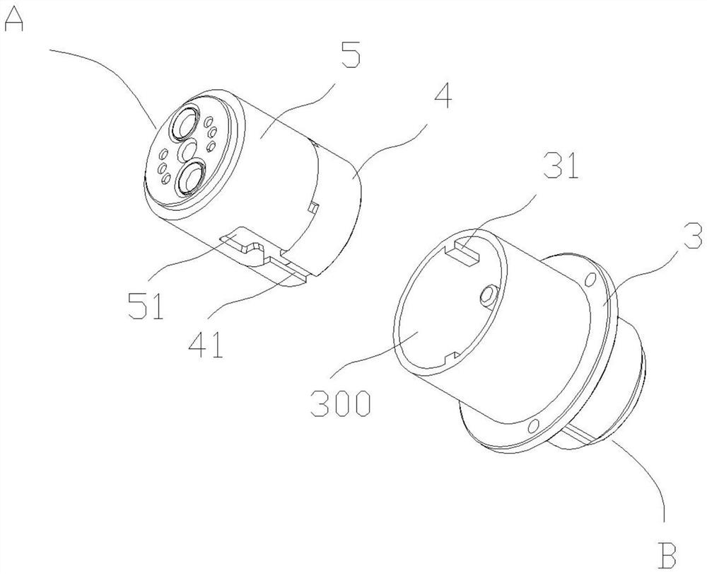
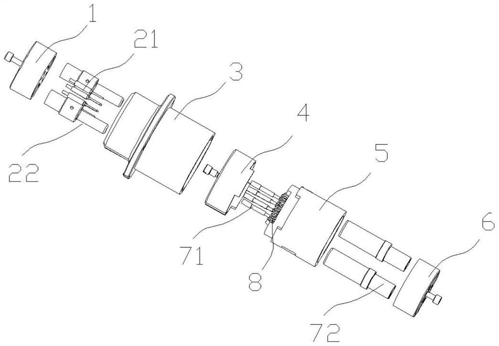
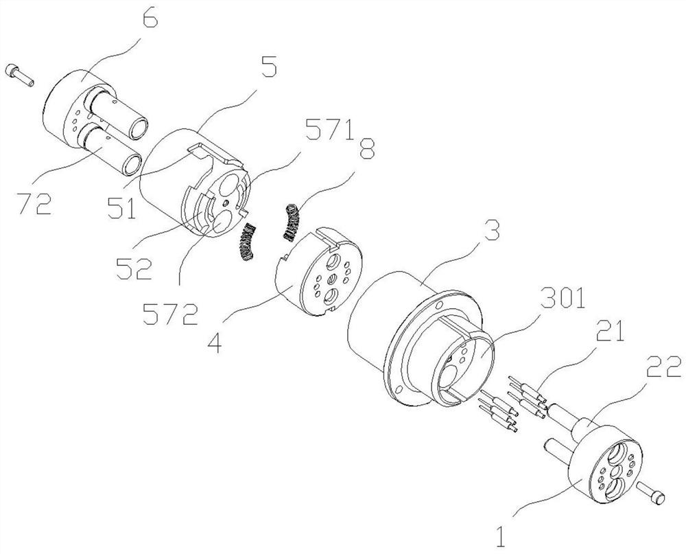
[0030] combine Figure 1 to Figure 3 As shown, this embodiment provides a rotary-side piezoelectric connector, including a plug A and a socket B that are mated with each other.

[0031] For ease of expression, in this...


PUM


Abstract

The invention provides a rotating side piezoelectric connector. The side piezoelectric connector comprises a first plugging assembly and a second plugging assembly, wherein the first plugging assemblycomprises a first insulating main body and a first plugging member, the second plugging assembly comprises a second insulating main body and a second plugging member, the second plug-in assembly further comprises a rotary end cover and an elastic piece, the rotary end cover can be rotatably installed on the second insulating main body to form a spinning mechanism in a matched mode, the elastic piece is arranged between the second insulating main body and the rotary end cover and is arranged at the position where circumferential torque is applied to the rotary end cover, and the second plug connector is arranged on the second insulating main body and is laterally pressed by matching of the rotating end cover and the insulating main body. The side piezoelectric connector is advantaged in that under the action of circumferential torque, the rotary end cover is laterally pressed on the first plug connector / pin terminal to realize connection so that contact stability is ensured.

Description

technical field [0001] The invention belongs to the technical field of electrical connectors, and in particular relates to a piezoelectric connector on a rotating side with stable contact and normal stress of pin terminals. Background technique [0002] For current connector products, in order to achieve stable electrical connection performance between sockets and plugs, rigid pins are often used in terminal design to cooperate with jacks or elastic jacks equipped with elastic elements (such as split slot jacks, crown spring jacks, etc.), or It adopts the structural form that the pin with the elastic element is matched with the rigid socket. [0003] For this type of connector product, on the one hand, the elastic element puts forward higher requirements on materials, structural design, and technology; on the other hand, the production and assembly of the elastic element consumes more manpower, equipment, and time costs. [0004] Therefore, there is an urgent need for an el...

Claims


Application Information

Patent Timeline
Patent Type & Authority Applications(China)
IPC IPC(8): H01R13/625H01R13/502H01R24/00
CPCH01R13/502H01R13/625H01R24/00
Inventor 付良凯陈建聪郭小萍
Owner XIAMEN WAIN ELECTRICAL
Why Eureka
Try Eureka