Method for optimizing structural parameters of visible light communication optical receiving antenna

An optical receiving antenna, visible light communication technology, applied in electromagnetic receivers, short-range systems, free space transmission, etc., to achieve the effect of improving performance, improving acquisition, and improving efficiency

Active Publication Date: 2020-10-30
FUDAN UNIV
View PDF10 Cites 0 Cited by
  • Summary
  • Abstract
  • Description
  • Claims
  • Application Information

AI Technical Summary

Problems solved by technology

In order to improve the receiving power and signal-to-noise ratio of the receiving end of the visible light communication system, and ensure a higher gain and a larger field of view, the industry at home and abroad has proposed various design ideas for optical antennas. The main direction of the research work is to design new antenna structures. However, there are almost no optimization methods applicable to the optical receiving antenna structure of visible light communication, and the proposal and research of optimization methods can also promote the improvement of system performance.

Method used


Image

  • Method for optimizing structural parameters of visible light communication optical receiving antenna
  • Method for optimizing structural parameters of visible light communication optical receiving antenna
  • Method for optimizing structural parameters of visible light communication optical receiving antenna

Examples


Embodiment

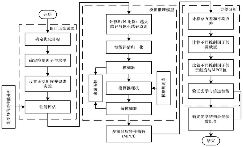
[0054] like figure 1 As shown in Fig. 1, an optimization method for structural parameters of an optical system includes three parts: Taguchi orthogonal experiment, fuzzy reasoning model and variance analysis. The main steps of the Taguchi orthogonal test include determining the optimization target, determining the control factor and level, setting the orthogonal matrix and completing the experiment and performance evaluation; the main steps of the fuzzy reasoning model include calculating the S / N ratio, and normalizing the performance evaluation. The main steps of the variance analysis include calculating the total variance and the average variance of the test, calculating the contribution of different control factors, and comparing different control factors. Factor contribution and MPCI value, verify optical and channel performance, and determine the optimal parameter combination of optical structure.

[0055] The calculation of the S / N ratio is based on the principle that t...


PUM


Abstract

The invention belongs to the technical field of optical antennas, and particularly relates to a method for optimizing structural parameters of a visible light communication optical receiving antenna.The method comprises the following three basic steps of a Taguchi orthogonal test determining an optimization target, determining a control factor and a level, setting an orthogonal matrix, and completing an experiment and performance evaluation; constructing a fuzzy inference model, including calculating an S / N proportion, normalizing performance evaluation, establishing a fuzzy device, a fuzzy inference machine and a defuzzifier, and obtaining multiple quality characteristic indexes; and variance analysis calculating a test total variance and an average variance, calculating contribution degrees of different control factors, comparing the contribution degrees of the different control factors with an MPCI value, verifying optical and channel performances, and determining an optimal parameter combination of an optical structure. According to the method, a problem of multi-quality characteristic trade-off when the optimal robust parameter combination of the optical structure is selectedcan be effectively solved, structural parameter optimization efficiency is greatly improved, and performance of an optical system can be greatly improved.

Description

technical field [0001] The invention belongs to the technical field of optical antennas, and in particular relates to a method for optimizing structural parameters of an optical system. Background technique [0002] Compared with traditional lighting methods, light-emitting diodes (LEDs) have the advantages of low power consumption, high brightness and long life, and have been widely used in various fields such as information display, visual transmission, and lighting. The rapid improvement in the performance of white LEDs has led to the emergence of a new wireless communication technology, that is, visible light communication technology. Compared with traditional radio frequency communication and other optical wireless communication methods, visible light communication is not limited by bandwidth, is not subject to electromagnetic interference from electronic equipment, has high security and confidentiality, and LED lighting communication equipment is easy to install, so it...

Claims


Application Information

Patent Timeline
Patent Type & Authority Applications(China)
IPC IPC(8): H04B10/116H04B10/67
CPCH04B10/116H04B10/67
Inventor 孔令豹彭星
Owner FUDAN UNIV
Why Eureka
Try Eureka