Washing and drying integrated hand dryer

A hand dryer and integrated technology, which is applied in the field of hand dryers, can solve the problems of single function, cumbersome drying process, and low drying efficiency, and achieve the effects of saving water resources, comfortable hand feeling, and improving drying efficiency

Pending Publication Date: 2020-11-03
제지앙인터하사인텔리전트테크놀로지컴퍼니리미티드
View PDF0 Cites 0 Cited by
  • Summary
  • Abstract
  • Description
  • Claims
  • Application Information

AI Technical Summary

Problems solved by technology

[0002] Hand dryers are generally used in homes, hotels or other public places. The opening of the existing hand dryers is generally set in front of the hand dryer, and the air is blown from top to bottom to dry the hands. , During the drying process, it is necessary to keep turning the palm of the hand to achieve the purpose of drying the front and back sides, so the drying efficiency is low, and it is easy to cause problems such as partial non-drying and cumbersome drying process;
[0003] In response to the above problems, an automatic hand dryer with the opening facing upwards was developed. Although this type of hand dryer can achieve double-sided air blowing, it will cause water droplets on the hands due to two parallel airflows when blowing air. While bl

Method used


Image

  • Washing and drying integrated hand dryer
  • Washing and drying integrated hand dryer
  • Washing and drying integrated hand dryer

Examples


Example Embodiment

[0035] The specific embodiments of the present invention will be described in further detail below in conjunction with the drawings and embodiments. The following examples are used to illustrate the present invention, but not to limit the scope of the present invention.
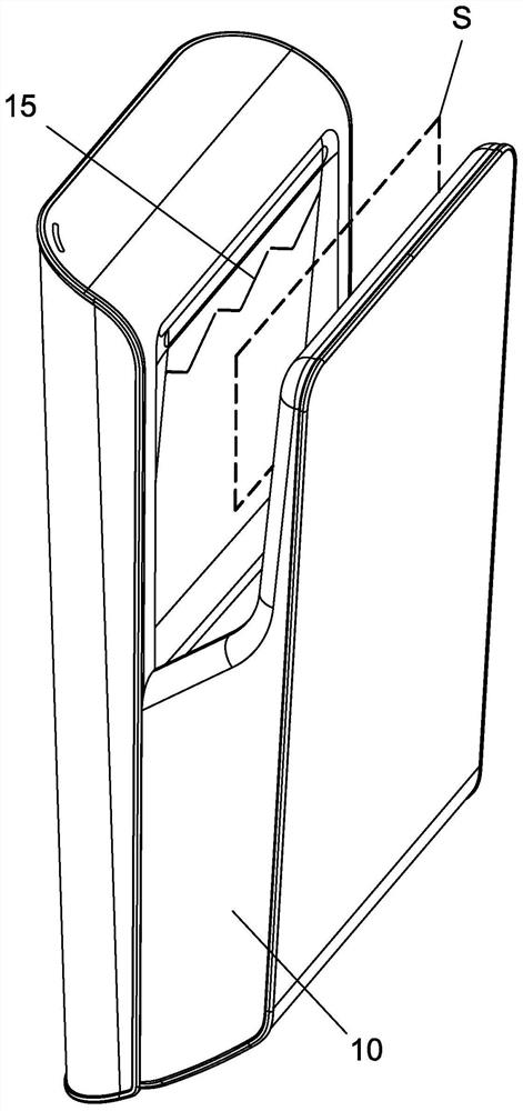
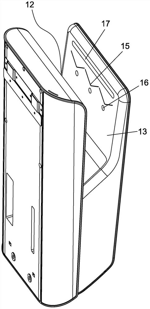
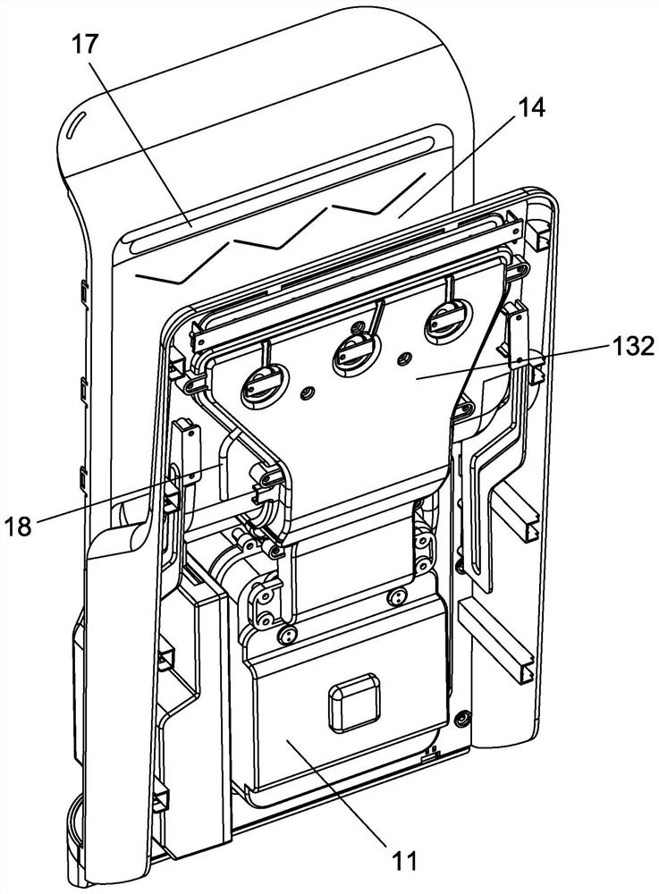
[0036] reference Figure 1 to Figure 9 ,Such as Figure 1 to Figure 9 An integrated hand dryer with washing and drying is shown, comprising a housing 10, a blower 11 is arranged in the housing 10, and the housing 10 is provided with an opening facing upward and penetrating the left and right sides of the housing 10 Hand drying trough 12, the front trough wall 13 and the rear trough wall 14 of the hand drying trough 12 are provided with an air outlet 15 at a position close to the top opening. The air outlet 15 is in the shape of one, and the cross section is wavy and free It is arranged from left to right or several, a single section is V-shaped and arranged from left to right; the side of the front groove wall...


PUM

PropertyMeasurementUnit
Angleaaaaaaaaaa

Abstract

The invention provides a washing and drying integrated hand dryer, which comprises a shell, an air blower is arranged in the shell, a hand drying groove with an upward opening and penetrating throughthe left side and the right side of the shell is formed in the shell; the positions, close to a top opening, of the front groove wall and the rear groove wall of the hand drying groove are each provided with an air outlet channel, the section of each air outlet channel is wavy and is arranged from left to right or a plurality of air outlet channels are arranged from left to right, and the sectionof each single air outlet channel is V-shaped and is arranged from left to right; a front air distribution channel used for supplying air to the air outlet channel in the front groove wall is formed in the face, back to the rear groove wall, of the front groove wall, and a rear air distribution channel used for supplying air to the air outlet channel in the rear groove wall is formed in the face,back to the front groove wall, of the rear groove wall. Water supply pipes are arranged in the front air distribution channel and the rear air distribution channel, water distribution pipes are arranged on the water supply pipes, and a plurality of capillary pipes communicated into the air outlet channel are arranged on the water distribution pipes. The washing and drying integrated hand dryer hasthe advantages of being capable of being used for washing hands, low in water consumption, high in drying efficiency and capable of increasing air flow and guaranteeing orderly blowing of water dropson the hands.

Description

technical field [0001] The invention relates to the field of hand dryers, in particular to a washing and drying integrated hand dryer. Background technique [0002] Hand dryers are generally used in homes, hotels or other public places. The opening of the existing hand dryers is generally set in front of the hand dryer, and the air is blown from top to bottom to dry the hands. , During the drying process, it is necessary to keep turning the palm of the hand to achieve the purpose of drying the front and back sides, so the drying efficiency is low, and it is easy to cause problems such as partial non-drying and cumbersome drying process; [0003] In response to the above problems, an automatic hand dryer with the opening facing upwards was developed. Although this type of hand dryer can achieve double-sided air blowing, it will cause water droplets on the hands due to two parallel airflows when blowing air. While blowing down, it makes irregular flow in the left and right di...

Claims


Application Information

Patent Timeline
IPC IPC(8): A47K7/04A47K10/48F21V33/00
CPCA47K7/04A47K10/48F21V33/004
Inventor 李作明唐伟朱灿锋钱和胜
Owner 제지앙인터하사인텔리전트테크놀로지컴퍼니리미티드
Why Eureka
Try Eureka