

Iron plate continuous bending machine
A technology of a bending machine and a bending mechanism, applied in the field of bending machines, can solve problems such as the inability to transfer iron plates, and achieve the effect of improving work efficiency and quality
- Summary
- Abstract
- Description
- Claims
- Application Information
AI Technical Summary
Problems solved by technology
Method used
Image

Examples
Embodiment 1
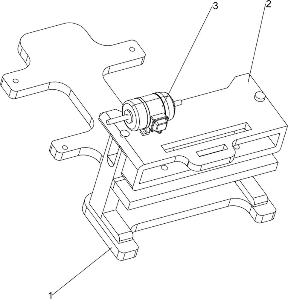
[0023] A continuous bending machine for iron plates, such as Figure 1-2 As shown, it includes a base 1, a workbench 2, a motor 3, a bending mechanism 4 and a pressing mechanism 5, a workbench 2 is arranged on the right side of the base 1, a motor 3 is arranged on the front side of the top of the workbench 2, and the output shaft of the motor 3 A bending mechanism 4 is connected with the workbench 2, and a pressing mechanism 5 is connected to the middle of the workbench 2, and the pressing mechanism 5 is connected with the bending mechanism 4.
[0024] When people need to bend the iron plate, start the motor 3, insert the iron plate between the bottom of the bending mechanism 4 and the pressing mechanism 5, and the rotation of the output shaft of the motor 3 drives the bending mechanism 4 and the pressing mechanism 5 to rotate continuously , so that the pressing mechanism 5 compresses the iron plate, and the bending mechanism 4 bends the iron plate. After the bending is succes...
Embodiment 2
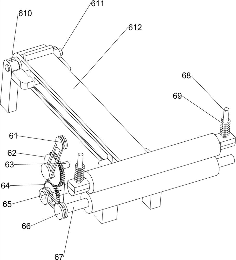
[0026] On the basis of Example 1, such as image 3 As shown, the bending mechanism 4 includes a bevel gear assembly 41, a first belt set 42, a first transmission shaft 43, a rotating disk 44, a long rod 45 and a pressing connection block 46, between the output shaft of the motor 3 and the pressing mechanism 5 A bevel gear assembly 41 is connected, and a first transmission shaft 43 is rotatably connected to the upper part of the workbench 2. A first belt set 42 is connected between the left part of the first transmission shaft 43 and the pressing mechanism 5, and the right part of the first transmission shaft 43 Connected with rotating disk 44, rotating disk 44 eccentric position is connected with long rod 45, and the right part of workbench 2 is slidingly connected with pressing connecting block 46, and pressing connecting block 46 top is connected with long rod 45 rotatingly.
[0027] When people need to bend the iron plate, start the motor 3, and the output shaft of the moto...
Embodiment 3
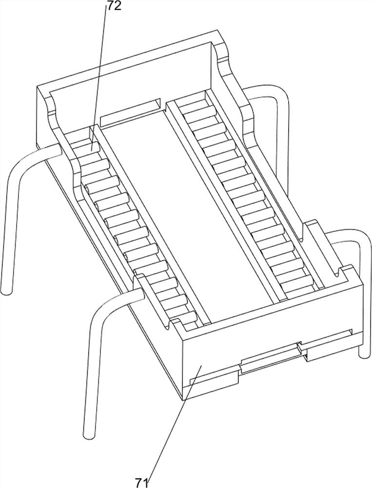
[0029] On the basis of Example 2, such as Figure 4-6 As shown, the pressing mechanism 5 includes a second transmission shaft 51, a cam 52, a pressing connection block 53 and a first compression spring 54, and the lower side of the workbench 2 is rotatably connected with the second transmission shaft 51, and the second transmission shaft 51 The left part is connected with the bevel gear assembly 41 and the first belt set 42, the right end of the second transmission shaft 51 is connected with a cam 52, the right part of the workbench 2 is slidingly connected with a compression connection block 53, and the top of the compression connection block 53 is connected to the cam 52 Extrusion contact, between the upper part of the compression connection block 53 and the top of the workbench 2 is connected with a first compression spring 54 , and the first compression springs 54 are all sleeved on the compression connection block 53 .
[0030] After the iron plate is placed in the middle...
PUM
 Abstract
Description
Claims
Application Information