A progressive loading precision forming die device and process method for complex components of ultra-long grid high-rib wall panels

A precision forming and meshing technology, applied in metal processing equipment, forging/pressing/hammer devices, manufacturing tools, etc., can solve problems such as billet flow burr, metal flow folding, upper die size limit, etc., to save die usage materials, flexible modifications, and reduced forging costs

Active Publication Date: 2021-11-30
HARBIN INST OF TECH +1
View PDF7 Cites 0 Cited by
  • Summary
  • Abstract
  • Description
  • Claims
  • Application Information

AI Technical Summary

Problems solved by technology

[0004] In the past, the local loading isothermal forming mold device and process method mainly used multiple combined upper dies for local loading. The patent of JPH05293581A divided the upper die into a stepped pressure plate and multiple inserts for forming the web. During the forming process, drag The stepped pressure plate causes the height difference between the inserts to form the web area of ​​the forging and press the unformed area. The boundary area between the inserts and the inserts of this upper die structure must be selected near the forging ribs. Otherwise, because there is a gap between the insert and the insert, the billet will flow into it and produce burrs, and the size of the upper die will be limited by the size of the forging
[0005] The patent of CN106134318B adopts the combination mold of inner mold and outer mold. The forming process is mainly divided into two steps. The first step is to use part of the mold to form part of the rib features of the forging. The second step is to assemble part of the mold into one After the mold is loaded as a whole, although the forming load is reduced, the size of the upper mold is not reduced, and in the second step of overall loading, because the formed area is not constrained by the mold, it will cause the metal in the unformed area to move toward the formed area. Regional flow produces folds

Method used


Image

  • A progressive loading precision forming die device and process method for complex components of ultra-long grid high-rib wall panels
  • A progressive loading precision forming die device and process method for complex components of ultra-long grid high-rib wall panels
  • A progressive loading precision forming die device and process method for complex components of ultra-long grid high-rib wall panels

Examples


Embodiment 1

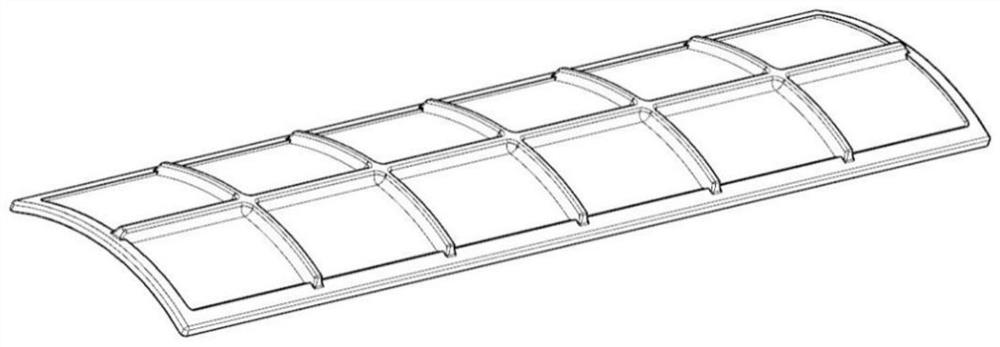
[0068] like Figure 1-10 As shown in the figure, taking a large mesh rib plate aluminum alloy member as an example, its shape is as follows figure 2 As shown, the part material is 5A06 aluminum alloy, the length of the component is 1100mm, the radius of the curved surface arc is 180mm, the central angle is 60°, there are 12 grids, each grid is 170mm long, 75mm wide, 4mm thick, and the ribs Height 10mm, rib width 10mm.

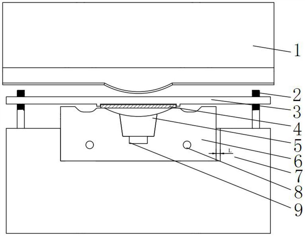
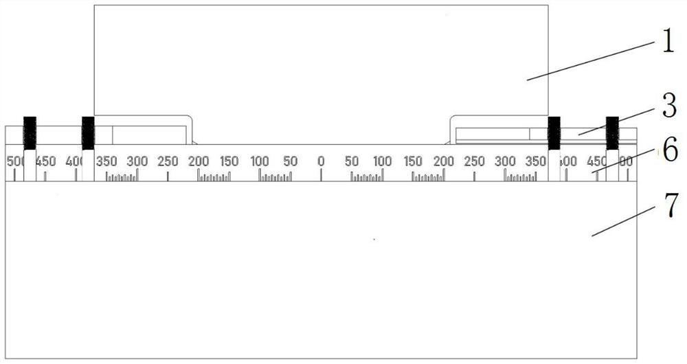
[0069] The progressive loading precision forming mold device for the complex component of the ultra-long grid high-rib wall plate in this embodiment includes a platen bolt 2, an insert 5, a mold core 6, a mold base 7, an upper mold 1, a first pressure plate 3, and a second pressure plate 12. , wedge iron 13, tie rod 14, the specific forming process is as follows image 3 and Figure 4 shown.

[0070] First, determine the blank size, the specific number of local loading and the order of local loading, loading length and loading zone location.

[0071] Dete...


PUM

PropertyMeasurementUnit
angleaaaaaaaaaa

Abstract

The invention discloses a progressively loaded precision forming mold device and a process method for complex components of ultra-long grid high-rib wall panels, and relates to the technical field of thermal processing, including an upper mold and a lower mold, and the upper mold is provided with a punch; The lower mold includes an insert, a mold core and a mold base, the upper surface of the mold base is provided with a mounting groove, the mold core is slidably installed in the installation groove, and the insert is installed on the upper surface of the mold core surface. The invention realizes the partial progressive loading of the forging on the single-action press through the horizontal sliding of the mold core on the mold base, reduces the size of the mold, and avoids the folding defect caused by the overall loading.

Description

technical field [0001] The invention relates to the technical field of thermal processing, in particular to a progressive loading precision forming die device and a process method for a complex component of an ultra-long grid high-rib wall plate. Background technique [0002] With the increasing requirements for high performance and light weight of carrying equipment and vehicles, lightweight and high-strength materials (such as aluminum alloys, titanium alloys, high-performance steels, etc.) and lightweight structures (such as Super long and complex structure) has become an effective way to improve its reliability and reduce its weight. [0003] For complex components such as ultra-long (longer than 1 meter) grid high-rib wall plates, long-shaft connecting rods or crankshafts, if the traditional integral forging method is used, a large-tonnage die forging press needs to be used, which will cause excessive forging forming loads. large, resulting in shortened die life. The ...

Claims


Application Information

Patent Timeline
Patent Type & Authority Patents(China)
IPC IPC(8): B21J13/02B21J1/06B21J5/02B21K29/00
CPCB21J1/06B21J5/025B21J13/02B21K29/00
Inventor 徐文臣李建伟徐佳炜单德彬郭卜瑞郭晓琳王志敏郭斌张铁军
Owner HARBIN INST OF TECH
Why Eureka
Try Eureka