Eureka AIR delivers breakthrough ideas for toughest innovation challenges, trusted by R&D personnel around the world.

Light chamber hybrid heating and refrigerating constant-temperature system

A technology of constant temperature system and optical chamber, applied in the field of spectrometer, can solve the problems of rising, single heating constant temperature, long heating time and temperature stabilization time, etc.

Pending Publication Date: 2020-11-03
JIANGSU SKYRAY INSTR
View PDF0 Cites 0 Cited by
  • Summary
  • Abstract
  • Description
  • Claims
  • Application Information

AI Technical Summary

Problems solved by technology

[0002] At present, the common method of constant temperature in the greenhouse for spectrometers on the market is to maintain the temperature of the heating element. The best constant temperature of the light chamber of the ICP instrument is 28-35°C. , and the temperature stability is not high. After long-term operation of the instrument, it is easy to cause the temperature of the optical chamber near the combustion chamber to rise continuously. The temperature rise is higher than the constant temperature, which makes the constant temperature invalid, which has a great impact on the measurement error of the spectrometer ; In order to further reduce the measurement error and ensure the uniformity of the temperature of the entire optical chamber, a semiconductor optical chamber heating and cooling constant temperature system is specially designed

Method used


Image

  • Light chamber hybrid heating and refrigerating constant-temperature system
  • Light chamber hybrid heating and refrigerating constant-temperature system
  • Light chamber hybrid heating and refrigerating constant-temperature system

Examples


Embodiment Construction

[0031] The present invention will be described in detail below in conjunction with the accompanying drawings and specific embodiments.

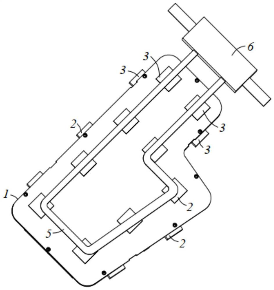
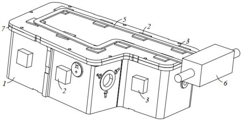
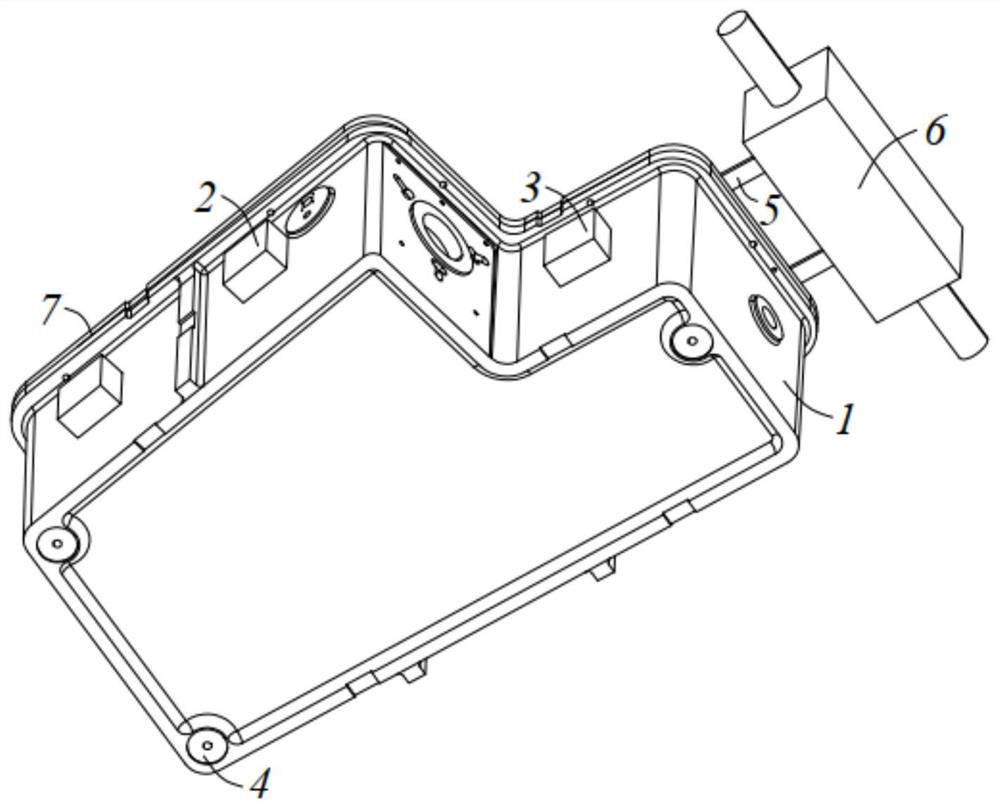
[0032] figure 1 , figure 2 and image 3 In order to solve the problems of the technologies described above, the present invention is achieved through the following technical solutions:

[0033] The mixed heating and cooling constant temperature system of optical chamber according to the present invention is applied to ICP spectrometer and is arranged beside the combustion chamber, such as figure 1 , figure 2 and image 3 As shown, it includes a light chamber 1, a number of heating elements 2, a temperature sensor corresponding to the heating elements 2, and an insulating material 7 arranged outside the light chamber 1. The light chamber 1 has a top surface, a bottom surface and a side surface, The bottom surface is partially concave to form a support part 4, the top surface is a plane, and the part between the top surface and the botto...


PUM


Abstract

The invention discloses a light chamber hybrid heating and refrigerating constant-temperature system which is arranged beside a combustion chamber and comprises a light chamber, a plurality of heatingcomponents, a temperature sensor and a heat preservation material; the heating components are arranged on the outer side surface of the light chamber, copper pipes are arranged on the heating components, and a heat exchange control module is arranged on one side of each copper pipe. The heating component close to one side of the combustion chamber is a semiconductor chilling plate; a room temperature sensor used for detecting the environment temperature of the outer side of the light chamber is arranged on the outer side of the light chamber, and a connecting position temperature sensor usedfor detecting the temperature of the connecting position is arranged on the connecting position of the light chamber and the combustion chamber. After judging is performed according to signals detected by the temperature sensor, the room temperature sensor and the temperature sensor at the joint, the work of each heating component is independently controlled; semiconductor heating and refrigeration belong to a heat exchange component, so that heat exchange needs to be performed through a copper pipe and water flow in the copper pipes, and a light chamber is uniform and constant-temperature.

Description

technical field [0001] The invention belongs to the field of spectrometers, and relates to a constant temperature system, in particular to a mixed heating and cooling constant temperature system for optical chambers. Background technique [0002] At present, the common method of constant temperature in the greenhouse for spectrometers on the market is to maintain the temperature of the heating element. The optimal constant temperature of the light chamber of the ICP instrument is 28-35°C. , and the temperature stability is not high. After long-term operation of the instrument, it is easy to cause the temperature of the optical chamber near the combustion chamber to rise continuously. The temperature rise is higher than the constant temperature, which makes the constant temperature invalid, which has a great impact on the measurement error of the spectrometer ; In order to further reduce the measurement error and ensure the uniformity of the temperature of the entire optical ...

Claims


Application Information

Patent Timeline
Patent Type & Authority Applications(China)
IPC IPC(8): G05D23/30
CPCG05D23/30
Inventor 应刚李正建解婉莹袁辉胡曦李胜辉
Owner JIANGSU SKYRAY INSTR
Why Eureka
Eureka Blog
Learn More