
Radiation rendering method and device for finite element model

A finite element and model technology, applied in the field of target infrared radiation simulation, can solve problems such as large deviation of normal direction and blurred edges of the target

Active Publication Date: 2020-11-03
BEIJING INST OF ENVIRONMENTAL FEATURES
View PDF12 Cites 1 Cited by
  • Summary
  • Abstract
  • Description
  • Claims
  • Application Information

AI Technical Summary

Problems solved by technology

[0005] The technical problem to be solved by the present invention is that in the existing method, the normal direction of the common vertex at the edge of the target deviates greatly from the normal direction of the real surface element, which causes the edge of the target to become blurred in the rendered imaging result. Defects in the prior art provide a radiation rendering method for smooth correction of the target finite element model

Method used


Image

  • Radiation rendering method and device for finite element model
  • Radiation rendering method and device for finite element model
  • Radiation rendering method and device for finite element model

Examples


Embodiment 1

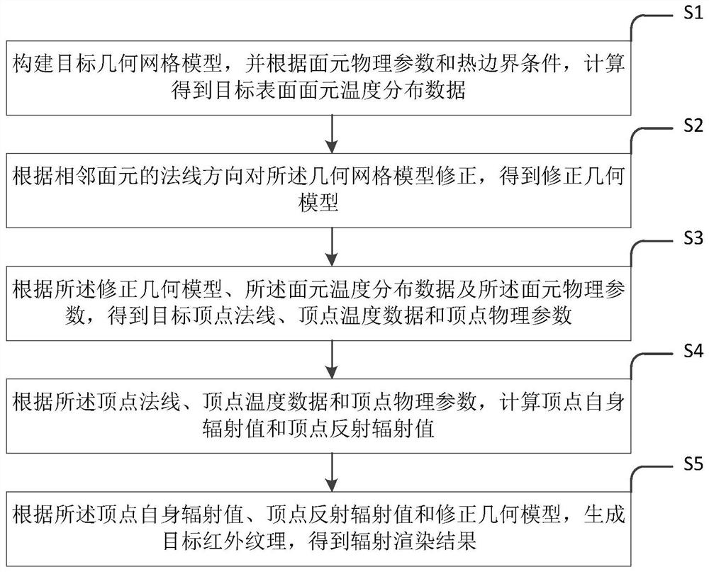
[0062] Such as figure 1 As shown, the radiation rendering method for the finite element model provided by the embodiment of the present invention includes the following steps:

[0063] Step S101 , constructing the target geometric mesh model, and calculating the target surface surface element temperature distribution data according to the surface element physical parameters and thermal boundary conditions.

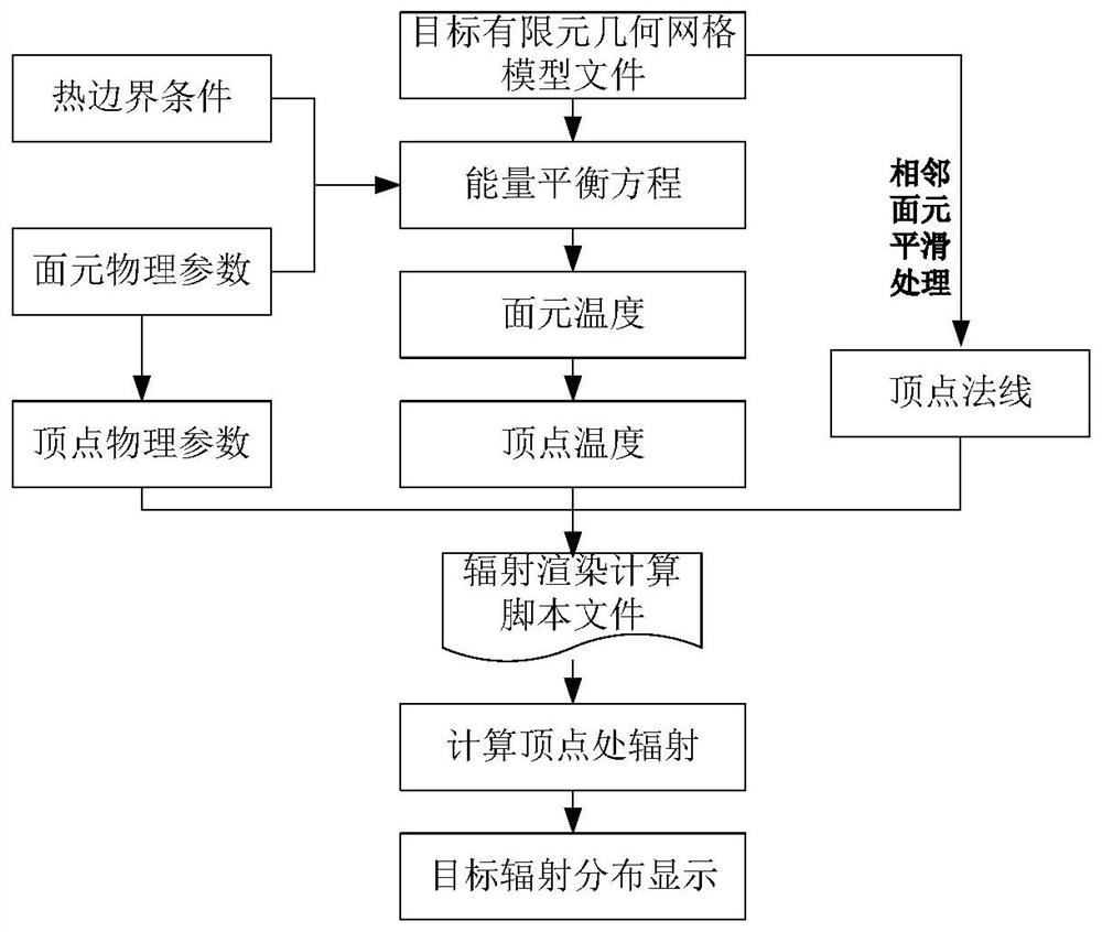
[0064] The present invention considers the influence of multiple reflections and spatial geometric positions when constructing the target finite element geometric grid model, and divides the target into a certain number of grid units according to the requirements of detection resolution and the like. Then establish the physical model of the target, that is, on the basis of the target mesh division, give the surface element physical parameters and thermal boundary conditions, and the surface element radiation heat exchange should consider two parts: the surface element's ow...

Embodiment 2

[0111] Such as Figure 8 The radiation rendering device for the finite element model provided by the second embodiment includes a model construction unit 100 , a model correction unit 200 , a vertex mapping unit 300 , a radiation calculation unit 400 and a rendering display unit 500 .

[0112] Wherein, the model construction unit 100 is used to construct the target geometric mesh model, and calculate and obtain target surface surface element temperature distribution data according to the surface element physical parameters and thermal boundary conditions.

[0113] In some preferred embodiments, according to the physical parameters of the surface element and the thermal boundary conditions, the temperature distribution data of the target surface surface element is calculated, which specifically includes:

[0114] According to the physical parameters of the panel and the thermal boundary conditions, the energy balance equation of each panel is obtained:

[0115] (G 1k ε 1k -J...


PUM


Abstract

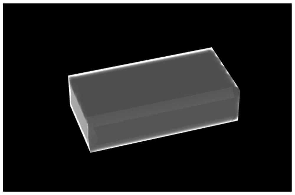
The invention relates to a radiation rendering method and device for a finite element model, and the method comprises the steps: building a target geometric grid model, and carrying out the calculation to obtain target surface element temperature distribution data according to surface element physical parameters and thermal boundary conditions; correcting the geometric grid model according to thenormal directions of the adjacent surface elements to obtain a corrected geometric model; obtaining a target vertex normal, vertex temperature data and vertex physical parameters according to the corrected geometric model, the surface element temperature distribution data and the surface element physical parameters, and then calculating a vertex self radiation value and a vertex reflection radiation value; and finally, generating a target infrared texture according to the vertex radiation value, the vertex reflection radiation value and the corrected geometric model to obtain a radiation rendering result. According to the method, excessive smoothing processing of adjacent surface elements at the edge of the target edge is avoided, and the simulation authenticity of a finite element model radiation rendering result is effectively improved.

Description

technical field [0001] The invention relates to the technical field of target infrared radiation simulation, in particular to a radiation rendering method and device for a finite element model. Background technique [0002] Theoretical modeling of target radiation characteristics is a more theoretical research method that comprehensively considers various effects. According to the structure of the target, various thermal and physical parameters of materials, and various environmental parameters of the environment, the target It must be divided into microelements, consider various physical processes, establish physical models, and solve numerically through mathematical methods and computers to obtain the radiation characteristics of the target. The theoretical model of target radiation characteristics can provide fast, economical and effective means for predicting the radiation characteristics of targets, the development of target infrared systems, and simulation design, and ...

Claims


Application Information

Patent Timeline
Patent Type & Authority Applications(China)
IPC IPC(8): G06F30/23G06F119/08
CPCG06F30/23G06F2119/08Y02E60/00
Inventor 林娟吴开峰马静刘兴润朱希娟吴杰李霞周越
Owner BEIJING INST OF ENVIRONMENTAL FEATURES
Learn More