Novel relay

A relay, a new type of technology, applied in the direction of relays, electromagnetic relays, detailed information of electromagnetic relays, etc., can solve problems such as unstable operation of auxiliary terminal components, and achieve the effects of enhancing work stability, reducing load, and increasing fault tolerance

Pending Publication Date: 2020-11-03
SANYOU CORP LTD +1
View PDF0 Cites 1 Cited by
  • Summary
  • Abstract
  • Description
  • Claims
  • Application Information

AI Technical Summary

Problems solved by technology

[0006] The purpose of the present invention is to provide a new type of relay in view of the deficiencies in the prior art, and the use of the relay can solve the problem of unstable operation of the auxiliary terminal assembly

Method used


Image

  • Novel relay
  • Novel relay
  • Novel relay

Examples


Embodiment 1

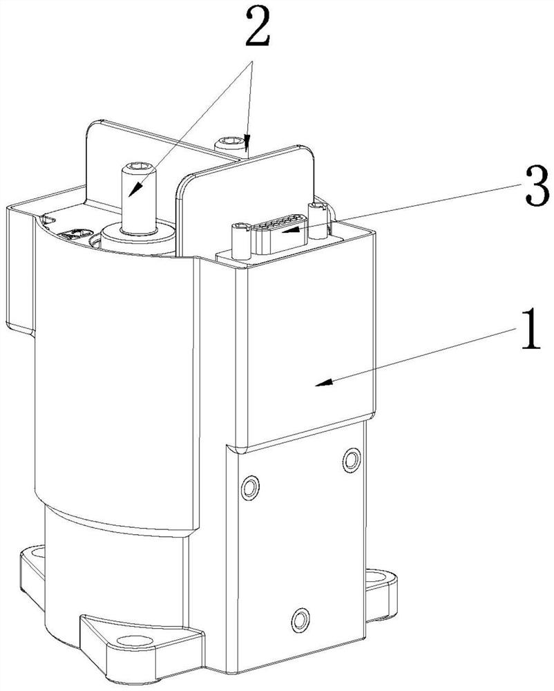
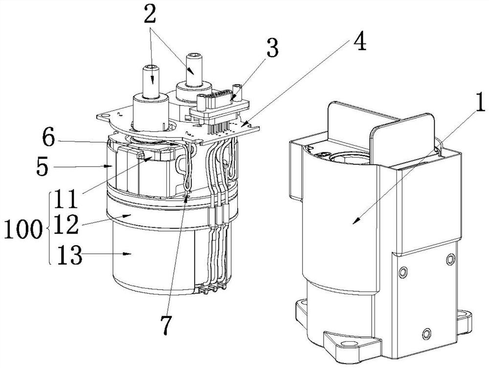
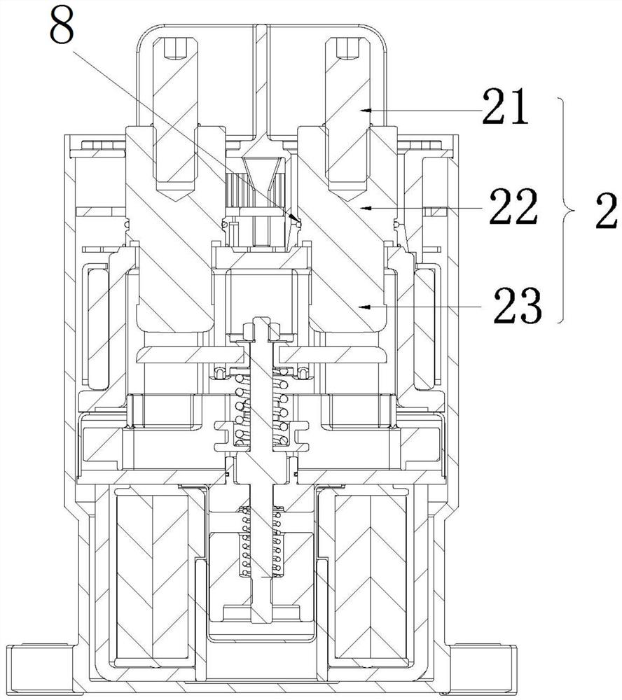
[0042] For a specific implementation of a novel relay of the present invention, see figure 1 and figure 2, the relay includes a housing 1 , a PCB board 4 , a magnetic frame 5 and a relay body 100 . The top of the relay body 100 is provided with a pair of static contact bridges 2 protruding to the top of the casing 1 , and the external terminals 3 for external connection are welded on the PCB 4 , and the external terminals 3 also pass through the casing 1 . The PCB board 4 is provided with perforations for the static contact bridge 2 to pass through, and the PCB board 4 is fixedly installed on the outer peripheral side of the static contact bridge 2, which can effectively shorten the distance between the static contact bridge 2 and the PCB board 4 and between the relay body 100 and the PCB board 4. The distance between the wires reduces the length required for the wires, which in turn reduces the wire resistance.

[0043] please see figure 2 1. A magnetic permeable frame 5...

Embodiment 2

[0062] The second specific embodiment of a novel relay of the present application, see Figure 15 or Figure 16 As shown, the main technical solutions of this embodiment are the same as those of Embodiment 1, and the features not explained in this embodiment are explained in Embodiment 1, and will not be repeated here. The difference between this embodiment and Embodiment 1 is that the outer peripheral side of the insulating holding member 92 extends out of the holding block 84 , and the end of the auxiliary movable contact piece 82 extends toward the insulating holding member and is wound around the outer periphery of the holding block 84 side. In this embodiment, the clamping block 84 is elongated, so that the overall structure of the insulating clamping member 92 is similar to that of the movable contact bridge 20 . Likewise, the auxiliary movable contact piece 82 and the auxiliary static contact piece 83 in this embodiment are both fixedly installed on the insulating sea...


PUM


Abstract

The invention relates to the technical field of relays, in particular to a novel relay, and the relay comprises a relay body, two static contact bridges, a movable contact bridge, a driving shaft, a driving mechanism and at least one auxiliary terminal assembly; the auxiliary terminal assembly comprises two auxiliary terminals, an insulating seat, an auxiliary movable contact piece, an auxiliary static contact piece and an insulating clamping piece; the insulating seat is fixed in the relay body, and the auxiliary movable contact piece and the auxiliary static contact piece are detachably installed on the insulating seat; a moving contact and a static contact are arranged at an interval in the height direction, the driving shaft is sleeved with an insulating clamping piece, and the end, provided with the moving contact, of the auxiliary moving contact piece extends towards the insulating clamping piece and is matched with the insulating clamping piece in a clamped mode. Compared with the prior art, a fixing mode that the auxiliary movable contact piece is fixed on the driving shaft is replaced, the load of the driving shaft is reduced, and the problem that the auxiliary movable contact piece falls off from the driving shaft is solved.

Description

technical field [0001] The invention relates to the technical field of relays, in particular to a novel relay. Background technique [0002] Existing relays generally include a ceramic case, a connection platform and a magnetic circuit case. The magnetic circuit case is used to load the coil and the top of the magnetic circuit case is provided with a supporting plate to separate the coil from the ceramic case, so that the ceramic case, the connection platform and the support The three plates are sealed and connected to form an arc extinguishing chamber, and the arc extinguishing chamber is provided with two static contact bridges, a moving contact bridge, a drive shaft and a drive mechanism. Two static contact bridges are fixedly installed on the ceramic shell, one end of the static contact bridge protrudes out of the ceramic shell, and the other end is inserted into the ceramic shell; the bottom end of the drive shaft passes through the supporting plate and is inserted into...

Claims


Application Information

Patent Timeline
Patent Type & Authority Applications(China)
IPC IPC(8): H01H50/54H01H50/64H01H50/08
CPCH01H50/08H01H50/541H01H50/647
Inventor 唐俊平周文亮张文政王亚宾
Owner SANYOU CORP LTD
Why Eureka
Try Eureka