
Duplex communication module of integrated waveguide isolator

A technology of duplex communication and integrated waveguide, which is applied in the field of duplex communication modules, can solve the problems of poor device matching, increased procurement costs, poor signal transmission, etc. Effect

Pending Publication Date: 2020-11-03
安徽阖煦微波技术有限公司
View PDF0 Cites 1 Cited by
  • Summary
  • Abstract
  • Description
  • Claims
  • Application Information

AI Technical Summary

Problems solved by technology

[0003] The current isolator is arranged outside the duplexer. The outside of the isolator needs to be equipped with a conversion device to connect the filter in the duplexer. The conversion device will increase the purchase cost. Assembly errors, high insertion loss, and low matching between devices make signal transmission poor

Method used


Image

  • Duplex communication module of integrated waveguide isolator
  • Duplex communication module of integrated waveguide isolator
  • Duplex communication module of integrated waveguide isolator

Examples


Embodiment 1

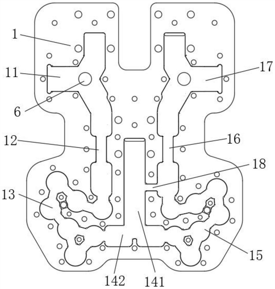
[0036] The receiving-end filter channel 15, the receiving-end low-pass 4 and the receiving-end isolator 5 are sequentially connected in series according to the order of signal transmission, the input end of the receiving-end filter channel 15 is connected to the common channel 14, and the return inlet of the coupling window 18 is located at Between the receiving end filter channel 15 and the receiving end low pass 4;

[0037]When this embodiment works,

[0038] When assembling, one of the two isolators is inserted into the installation slot 11 of the isolator at the transmitting end, and the other is inserted into the installation slot 17 of the isolator at the receiving end. One is embedded in the low-pass mounting groove 16 at the receiving end, and through the constraints of the mounting groove, the isolator and the low-pass can be inserted into the specified assembly position precisely, so that the isolator and the low-pass can be completed while the isolator and low-pass ...

Embodiment 2

[0041] The receiving end low pass 4, the receiving end filter channel 15 and the receiving end isolator 5 are serially connected in sequence according to the signal transmission sequence, the input end of the receiving end low pass 4 is connected to the common channel 14, and the return inlet of the coupling window 18 is located at Between the filter channel 15 at the receiving end and the isolator 5 at the receiving end.

[0042] When this embodiment works,

[0043] When assembling, one of the two isolators is inserted into the installation slot 11 of the isolator at the transmitting end, and the other is inserted into the installation slot 17 of the isolator at the receiving end. One is embedded in the low-pass installation groove 16 of the receiving end, and the specified assembly position that the isolator and the low-pass can be inserted accurately through the constraints of the installation groove, so that the isolator and the low-pass can be inserted into the isolator a...


PUM


Abstract

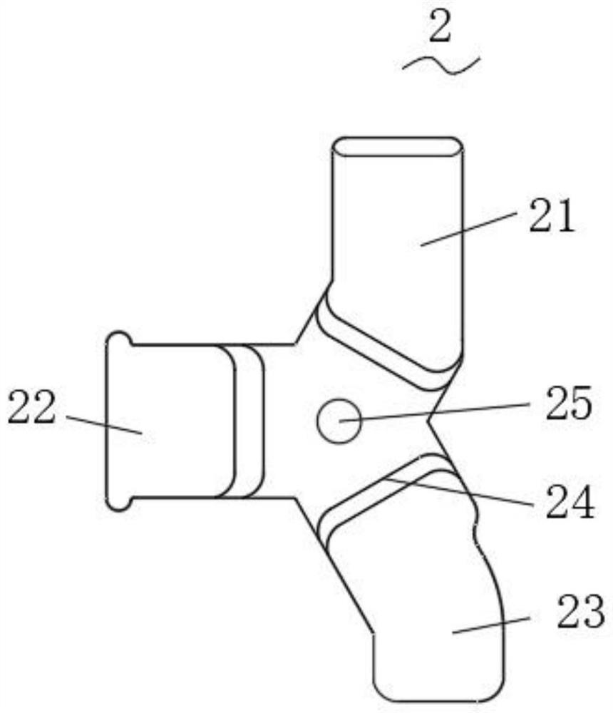
A duplex communication module of an integrated waveguide isolator comprises a cavity and a cover plate, a concave common channel is formed in the center line of the cavity, a transmitting channel is formed in one side of the common channel, a receiving channel is formed in the other side of the common channel, and the transmitting channel and the receiving channel are both formed in the cavity. The input end of the common channel is communicated with the output end of the transmitting channel, the output end of the common channel is communicated with the input end of the receiving channel, anda transmitting end isolator, a transmitting end low pass and a transmitting end filtering channel which are used for forming a microwave transmitting path are arranged in the transmitting channel. Areceiving end isolator for forming a microwave receiving path, a receiving end low pass and a receiving end filtering channel are arranged in the receiving channel. According to the invention, the isolator and the low-pass filter are arranged in the cavity of the duplexer, so the matching precision between the isolator and the filter can be effectively improved, and the performance loss of the system is reduced.

Description

technical field [0001] The invention belongs to the technical field of duplexers, in particular to a duplex communication module integrating waveguide isolators. Background technique [0002] Traditionally, increasing the communication rate of communication equipment and solving the problem of increasing the number of channels, simply increasing the bandwidth can no longer be realized, and the multi-system solution is a good choice. Multiple sets of systems working at the same time can double the communication rate, thereby improving the reliability and stability of the equipment. The structure of the microwave transceiver system is mainly composed of the isolator of the antenna waveguide and the duplexer for mutual conversion and connection; [0003] The current isolator is arranged outside the duplexer. The outside of the isolator needs to be equipped with a conversion device to connect the filter in the duplexer. The conversion device will increase the purchase cost. As...

Claims


Application Information

Patent Timeline
Patent Type & Authority Applications(China)
IPC IPC(8): H04B1/38H04L5/14
CPCH04B1/38H04L5/14
Inventor 杨宋兵李慧勇廉嘉乐
Owner 安徽阖煦微波技术有限公司
Learn More