Liquid-cooled heat exchange system

A technology of cold and heat exchange and hot zone, applied in cooling/ventilation/heating renovation, electrical components, electrical equipment structural parts, etc. , to avoid the waste of heat leakage, shorten the heat flow path, and solve the effect of hot spot concentration and heat island effect

Pending Publication Date: 2020-11-03
SHENZHEN KEXIN COMM TECH
View PDF0 Cites 0 Cited by
  • Summary
  • Abstract
  • Description
  • Claims
  • Application Information

AI Technical Summary

Problems solved by technology

[0004] The purpose of the present invention is to provide a liquid-cooled heat exchange system to solve the technical problems existing in the prior art that communication equipment is prone to hot spot concentration and heat island effect, mixing of hot and cold air and waste of heat leakage

Method used


Image

  • Liquid-cooled heat exchange system
  • Liquid-cooled heat exchange system
  • Liquid-cooled heat exchange system

Examples


Embodiment approach

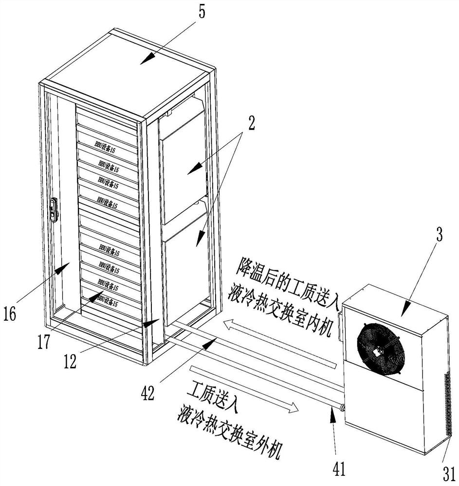
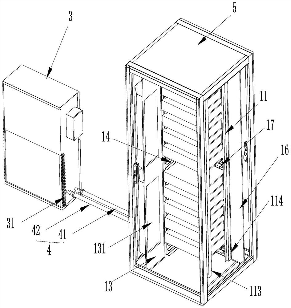
[0048] Furthermore, please also refer to Figure 2 to Figure 6 , as a specific embodiment of the liquid cooling heat exchange system provided by the present invention, the cabinet system includes an equipment carrying frame 11, a first partition 12, a second partition 13 and a first closing plate 14, the equipment The cabinet 5 includes a front cabinet door 51, a rear cabinet door 52, a left cabinet door 53 and a right cabinet door 54, and the equipment carrying frame 11 includes a first pillar 111, a second pillar 112, a third pillar 113 and a fourth pillar 114 ; The first pillar 111, the second pillar 112, the third pillar 113 and the fourth pillar 114 encircle the equipment carrying frame 11 in turn, and the equipment carrying frame 11 is installed in the equipment cabinet 5, so A plurality of BBU devices 15 are placed on the device carrying rack 11, the first closed plate 14 is arranged between two adjacent BBU devices 15, and the first closed plate 14 and the BBU device 1...

specific Embodiment approach

[0051] Furthermore, please also refer to Figure 2 to Figure 6 , as a specific embodiment of the liquid cooling heat exchange system provided by the present invention, the cabinet system further includes a third partition 16 and a second closing plate 17;

[0052] The third partition 16 is arranged between the fourth pillar 114 and the left cabinet door 53, the second closing plate 17 is arranged between two adjacent BBU devices 15, and the third partition The plate 16 and the second closing plate 17 are all coplanar with the front side of the BBU equipment 15; , and the area surrounded by the front cabinet door 51 is the front isolation area 18; the left area of ​​the BBU equipment 15 communicates with the rear side area of ​​the BBU equipment 15, and the second partition 13, the second The area enclosed by the three partitions 16 , the BBU equipment 15 , the equipment carrying rack 11 , the left cabinet door 53 and the rear cabinet door 52 is a cold zone 56 .

[0053] Exem...


PUM


Abstract

The invention provides a liquid-cooled heat exchange system which comprises an equipment cabinet system, a liquid-cooled heat exchange indoor unit, a liquid-cooled heat exchange outdoor unit and a pipeline; hot air in the hot area exchanges heat with the liquid-cooled heat exchange indoor unit to form heat, then the heat is transferred to a working medium flowing in the liquid-cooled heat exchangeindoor unit; the working medium circulates between the liquid-cooled heat exchange indoor unit and the liquid-cooled heat exchange outdoor unit through a pipeline, and the liquid-cooled heat exchangeoutdoor unit dissipates the heat of the working medium into the external environment; finally, the working medium returns to the liquid-cooled heat exchange indoor unit through a pipeline after beingcooled, the liquid-cooled heat exchange indoor unit conducts heat exchange on the cooling capacity of the working medium to form cold air, and the cold air is exhausted to a cold area of the equipment cabinet. According to the liquid cold-heat exchange system, hot air discharged from the hot area passes through the cold-heat exchange system to form cold air to flow back to the cold area, an independent closed circulating system is formed, wherein the hot air in the hot area directly enters the liquid cold-heat exchange system to shorten a heat flow path to the maximum extent, and the problemsof hot spot concentration and heat island effect are solved.

Description

technical field [0001] The invention belongs to the field of communication equipment, and more specifically relates to a liquid cooling heat exchange system. Background technique [0002] With the development and progress of communication technology, the advancement of the 5G market, the continuous growth of the network broadband market and business volume, as 5G gradually approaches, the power consumption capacity of 5G equipment will increase exponentially, and the bandwidth of a single base station will increase significantly. As the density increases, the existing base station network construction methods have shown some problems. [0003] At present, in traditional communication base stations, there are generally two ways of centralized placement and cooling and heat dissipation of communication equipment. One is to use the original traditional integrated pallet method to use the air conditioner in the equipment room for cooling and heat dissipation. The other is to ce...

Claims


Application Information

Patent Timeline
Patent Type & Authority Applications(China)
IPC IPC(8): H05K7/20
CPCH05K7/20763
Inventor 曾剑鹏刘刚可罗华平陈宇峰陈登志赵毓毅
Owner SHENZHEN KEXIN COMM TECH
Why Eureka
Try Eureka