Cutting device for grafting solanaceae vegetables

A cutting device and vegetable technology, applied in grafting and other directions, can solve the problems of inaccurate control of cutting distance, easy to cut fingers, etc., and achieve the effect of avoiding inaccurate cutting positioning and high cutting efficiency.

Inactive Publication Date: 2020-11-06
张国玉
View PDF0 Cites 4 Cited by
  • Summary
  • Abstract
  • Description
  • Claims
  • Application Information

AI Technical Summary

Benefits of technology

This new type of machine has several technical features compared to previous machines used for this purpose. One advantage it provides over existing methods is its ability to automatically adjust the depth at which each part needs to be severely trimmed based upon factors like growth rate and environmental conditions such as temperature. Another important aspect being mentioned is how well control the amount of power needed during operation without causing harm if there's any human error involved while manually moving the parts between different positions within the system.

Problems solved by technology

The technical problem addressed in this patented text relates to improving the efficiency at which crops can produce tomatoes (Solanserum), particularly solanesia type tomato varieties grown for commercial sale on crop landings during winter months when temperatures may drop below freezing. Current techniques involve manually shaping the roots with knives before they start growing from seedling stems. This process requires skilled workers who have special training and skill levels over time.

Method used


Image

  • Cutting device for grafting solanaceae vegetables
  • Cutting device for grafting solanaceae vegetables
  • Cutting device for grafting solanaceae vegetables

Examples


Embodiment 1

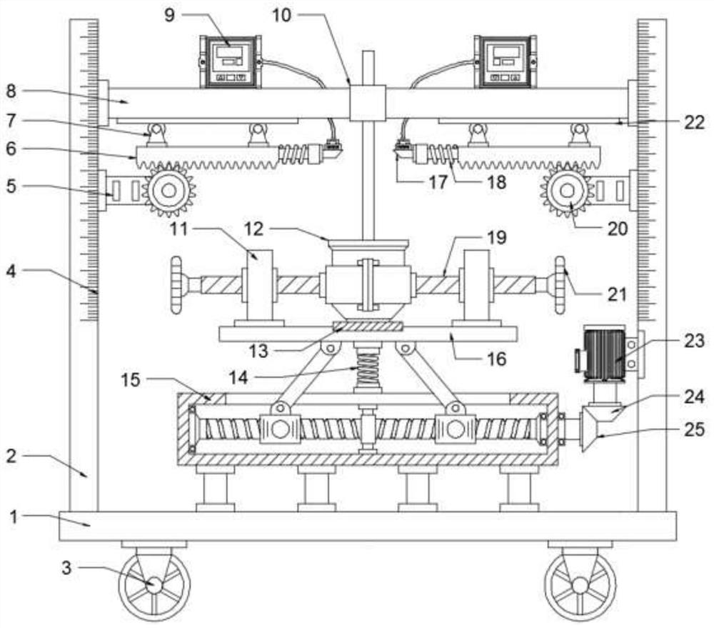
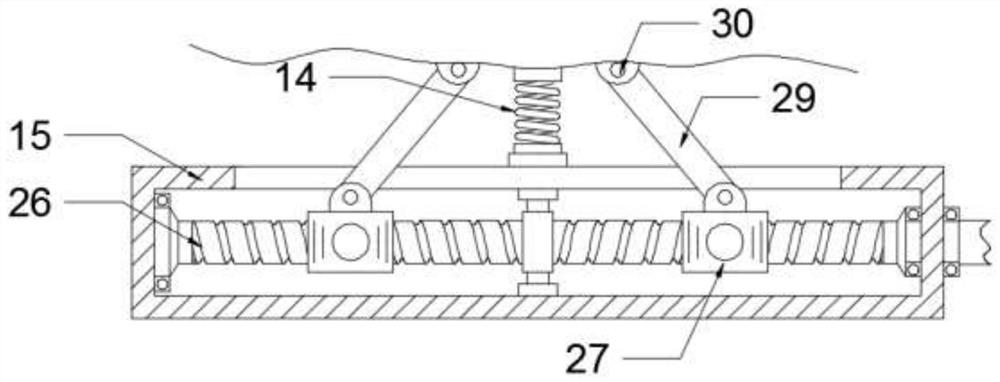
[0024] see Figure 1-4 , a cutting device for grafting Solanaceae vegetables, comprising a base 1 and a cutter 17, brackets 2 are symmetrically arranged on the left and right sides of the upper surface of the base 1, the bracket 2 and the base 1 are fixedly connected by welding, and the left and right sides The lifting box 15 is set between the two supports, and the lifting box 15 is fixedly connected with the base 1 through a connecting rod. The screw rod 26 is arranged in the lifting box 15, and the screw rod 26 is rotatably connected with the inner walls of the left and right sides of the lifting box 15. Screw rod 26 left and right sides thread direction is opposite, described screw rod 26 surface left and right sides symmetrically set movable seat 27, described movable seat 27 can move in horizontal direction along with the rotation of screw rod 26, described screw rod 26 right end passes through lift Box 15 is extended and fixedly connected to bevel gear 1 25, and drive m...

Embodiment 2

[0033] see Figure 1-2, on the basis of embodiment 1, in order to carry out raising and lowering to Solanaceae vegetable cultivation pot 12, adjust stem branch to suitable distance and then cut, rotate by driving motor one 23, and described driving motor one 23 drives bevel gear two 24 to rotate , the bevel gear two 24 drives the bevel gear one 25 to rotate, and the bevel gear one 25 drives the screw rod 26 to rotate, and the movable seats 27 on the left and right sides are close to or far away from each other on the surface of the screw rod 26. 30 promotes the cutting platform 16 to move up and down in the vertical direction to realize the lifting of the Solanaceae vegetable cultivating pot 12.

[0034] Further, in order to improve the stability of the cutting platform 16 during the up and down movement, in this embodiment, a damping spring 14 is fixedly installed between the cutting platform 16 and the lifting box 15 .


PUM


Abstract

The invention discloses a cutting device for grafting solanaceae vegetables, and relates to the technical field of vegetable planting auxiliary equipment. The cutting device comprises a base and cutters, wherein supports are arranged on the upper surface of the base; a lifting box is arranged between the supports on the left and right sides; the lifting box is fixedly connected with the base through a connecting rod; a screw is arranged in the lifting box, and cutting platforms are arranged above and below the lifting box; supporting bases are symmetrically installed on the left side and the right side of the upper surface of each cutting platform; fastening lead screws are installed in the supporting bases; arc-shaped clamps are fixedly connected to the tail ends of the sides, close to each other, of the fastening lead screws; second driving motors are arranged between the supports; a gear is fixedly connected to the tail end of an output shaft of each second driving motor; tooth-shaped plates are arranged above the gears; the tail ends of the sides, close to each other, of the tooth-shaped plates are connected with the cutters; the cutting platforms are pushed to move up and downin the vertical direction through lifting rods and hinge bases, the cutting height of stems and branches in a solanaceae vegetable cultivation pot is adjusted, the tooth-shaped plates push the cutters to move inwards for cutting, the cutting efficiency is higher, and the cutters cannot hurt personnel.

Description


Claims


Application Information

Patent Timeline
Owner 张国玉
Why Eureka
Try Eureka