Anesthetic needle inserting device for anesthesiology department
A technology of anesthesia needle and anesthesiology department, which is applied in the field of medical anesthesia, can solve the problems of too deep insertion of anesthesia needle, increase the pain and danger of patients, and achieve the effect of saving time and relieving pain
- Summary
- Abstract
- Description
- Claims
- Application Information
AI Technical Summary
Problems solved by technology
Method used
Image
Examples
Embodiment 1
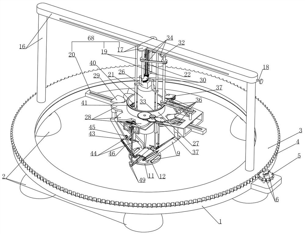
[0042] Embodiment 1, this embodiment provides an anesthesia needle insertion device for anesthesiology department, refer to the attached figure 1 As shown, including the bearing ring 1, we installed a number of suction cups 2 around the bottom of the bearing ring 1 at intervals. When injecting anesthesia for the patient, we placed the bearing ring 1 on the injection site of the patient and pressed down the suction cup 2 firmly so that The air between the suction cup 2 and the patient's body is discharged outward, so that the bearing ring 1 is firmly positioned at the patient's injection site under the action of atmospheric pressure (it should be noted here that this device is only aimed at the patient's abdomen, chest, It is used for anesthesia injections in large areas such as the waist, and it is not recommended to use this device for injections on the patient's face, fingers, and feet);
[0043] It is characterized in that we rotate an adjusting ring 3 on the bearing ring 1...
Embodiment 2
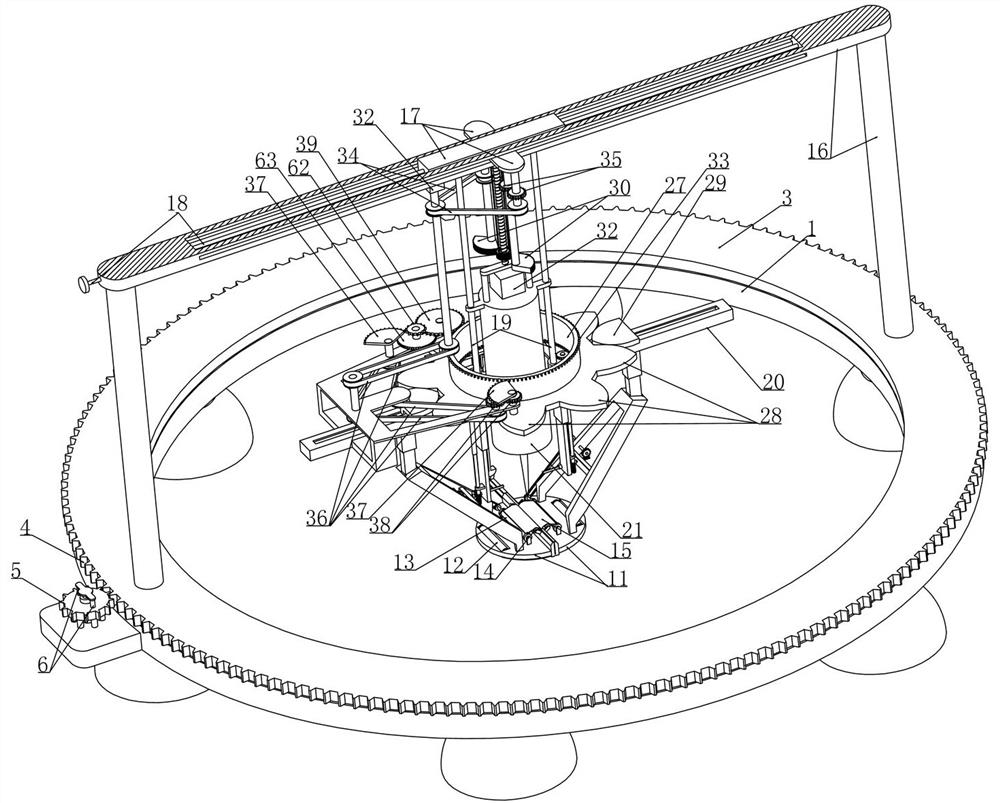
[0047] Embodiment 2, on the basis of embodiment 1, with reference to appended figure 1 As shown, we fixedly install a U-shaped frame 16 arranged along its radial direction on the upper end surface of the adjustment ring 3, referring to the attached figure 1 , 2 As shown, the bearing frame 68 includes a slider 17 slidably installed on the horizontal part of the U-shaped frame 16 and the bottom of the slider 17 is fixed with two vertically extending round bars 19 at intervals. The bearing rod 20 extending radially from the ring 1, the injection device includes the injection cylinder 21 which is vertically slidably fitted with the two round rods 19 (we set the injection cylinder 21 coaxially with the bearing ring 1 when setting), refer to the attached Figure 18 As shown, we have a push plate 24 axially slidably installed in the injection cylinder 21 and the push plate 24 is threaded with a screw 25 that is rotatably installed in the injection cylinder 21, and the screw 25 is fi...
Embodiment 3
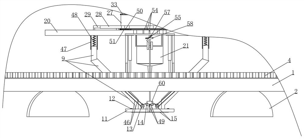
[0050] Embodiment 3, on the basis of embodiment 2, with reference to appended Figure 8 As shown, the reciprocating transmission device includes a cylinder 27 that is rotatably mounted on two bearing rods 20 and coaxially arranged with the injection cylinder 21, and arc-shaped protrusions 28 are arranged around the outer surface of the bottom of the cylinder 27 at intervals. A back-moving spring 10 is connected between the auxiliary frame 9 and the bearing rod 20, and the upper end of the auxiliary frame 9 is fixed with an arc-shaped plate 29 matched with the arc-shaped protrusion 28. When we set the initial state, the two matched semicircular plates 11 are in the Mutual conflict state, that is, at this time, the arc-shaped plate 29 fixedly installed on the upper end of the auxiliary frame 9 just interferes with the position between the adjacent two arc-shaped protrusions 28 arranged on the cylinder 27 (as attached Figure 8 As shown), in specific work, when the intermittent d...
PUM
 Abstract
Description
Claims
Application Information
 - R&D
- Intellectual Property
- Life Sciences
- Materials
- Tech Scout
- Unparalleled Data Quality
- Higher Quality Content
- 60% Fewer Hallucinations
Browse by: Latest US Patents, China's latest patents, Technical Efficacy Thesaurus, Application Domain, Technology Topic, Popular Technical Reports.
© 2025 PatSnap. All rights reserved.Legal|Privacy policy|Modern Slavery Act Transparency Statement|Sitemap|About US| Contact US: help@patsnap.com


