Washing device for drilling equipment

A cleaning device and equipment technology, which is applied in the direction of lighting and heating equipment, drying gas arrangement, cleaning method and utensils, etc., can solve the problems such as difficult cleaning of drill bits and difficult removal of sundries, and achieve the effect of fast putting into use and accelerating drying

Inactive Publication Date: 2020-11-06
SINOPEC SHENGLI PETROLEUM ENG
View PDF8 Cites 3 Cited by
  • Summary
  • Abstract
  • Description
  • Claims
  • Application Information

AI Technical Summary

Problems solved by technology

[0003] Most of the existing patents for drilling equipment cleaning devices on the market have the following deficiencies: the drill bit is not easy to clean, and the sundries are not easy to remove, and existing patents are not easy to solve such problems. Therefore, there is an urgent need for a drilling equipment cleaning device. solve the above problems

Method used


Image

  • Washing device for drilling equipment
  • Washing device for drilling equipment
  • Washing device for drilling equipment

Examples


Embodiment 1

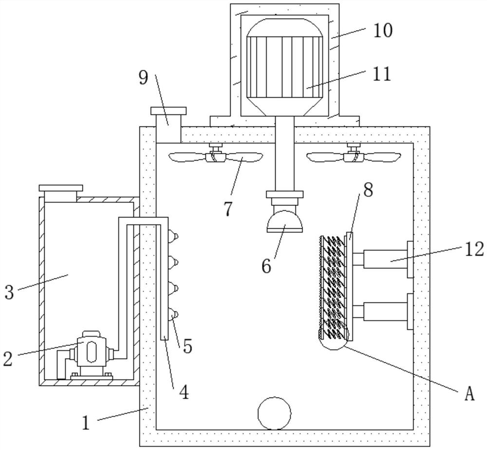
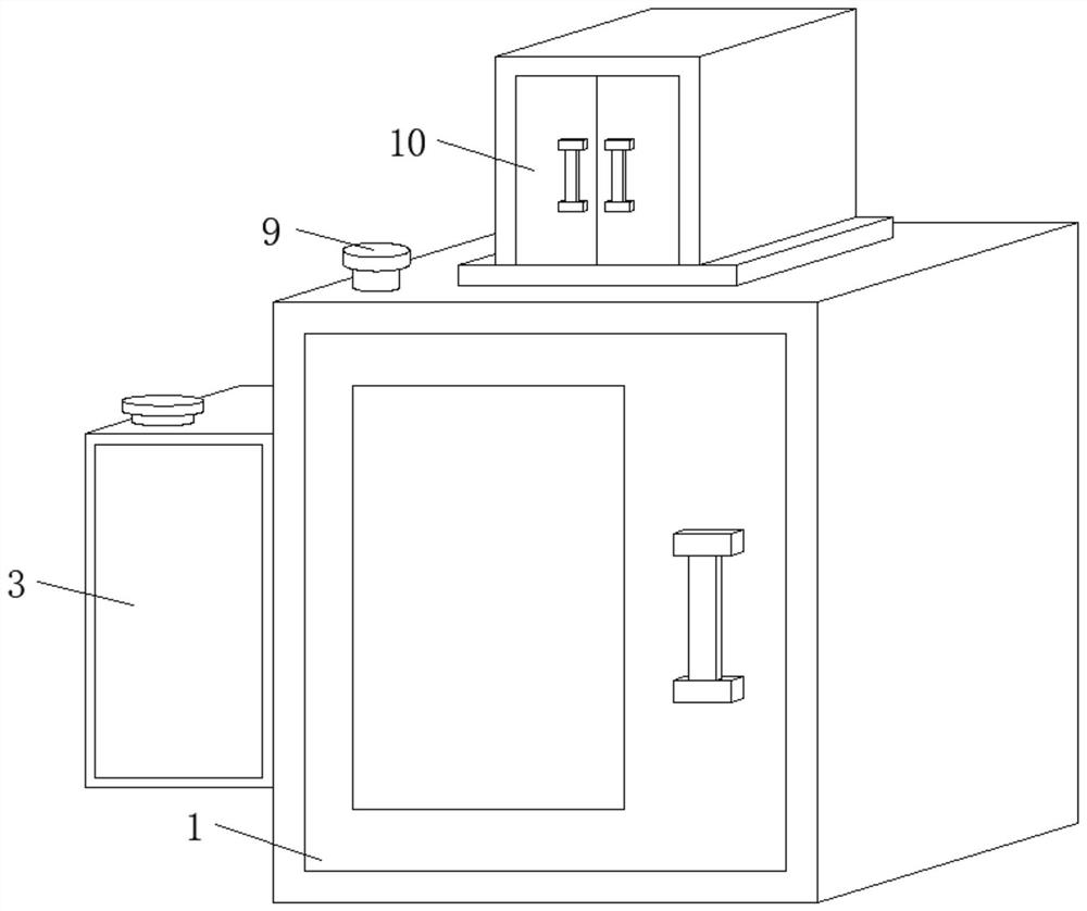
[0024] refer to Figure 1-3 , a cleaning device for drilling equipment, comprising a box body 1, a flushing mechanism is provided on one side of the outer wall of the box body 1, a motor box 10 is fixed on the middle position of the top outer wall of the box body 1 by bolts, and the bottom inner wall of the motor box 10 passes through The motor 11 is fixed by bolts, and one end of the output shaft of the motor 11 is keyed to a transmission shaft. One end of the transmission shaft is located inside the box body 1, and one end of the transmission shaft is fixed with an electromagnetic chuck 6 by bolts. The side of the box body 1 away from the flushing mechanism There is a scrubbing mechanism on the inner wall, fans 7 are fixed by bolts on both sides of the inner wall of the top of the box body 1, a box door is hinged on one side of the outer wall of the box body 1, and a box door is inserted on one side of the outer wall of the box body 1 near the bottom. drain pipe.

[0025] I...

Embodiment 2

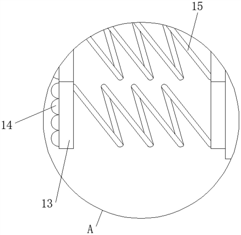
[0028] refer to Figure 4 , a cleaning device for drilling equipment. Compared with Embodiment 1, in this embodiment, a heater 17 is fixed on one side of the outer wall of the box body 1 near the top by bolts, and an air bucket 18 is plugged into one end of the heater 17. One end of bucket 18 is positioned at the inside of box body 1, and fan 16 is fixed with bolt on one side outer wall of heater 17, and the output end of fan 16 communicates with the inside of heater 17.

[0029] During use, after the drill bit is cleaned, start the heater 17 to heat, and then the blower fan 16 blows air to bring the heat into the inside of the box body 1 to dry the drill bit so that it reaches a dry state quickly. Drying is for checking the drill bit. Check the wear condition to see if it can be reused. Whether the drill bit is dry or not will not affect its use. The purpose is to prevent the damaged drill bit from being put into use.


PUM


Abstract

The invention discloses a washing device for drilling equipment. Aiming at the problems that a drill bit is not easy to clean and sundries are not easy to remove, the following technical scheme is provided: the washing device comprises a box body, a flushing mechanism is arranged on the outer wall of one side of the box body, a motor box is fixed to the middle position of the outer wall of the topof the box body through bolts, a motor is fixed to the inner wall of the bottom of the motor box through bolts, one end of an output shaft of the motor is in key connection with a transmission shaft,one end of the transmission shaft is located in the box body, an electromagnetic chuck is fixed to one end of the transmission shaft through bolts, a brushing mechanism is arranged on the inner wallof the side, away from the flushing mechanism, of the box body, and fans are fixed to two sides of the inner wall of the top of the box body through bolts. After electric telescopic rods are fed intothe surface wall of the drill bit, slight extrusion is carried out, different spring plates carry out extrusion to different degrees according to the shape of the drill bit and attach to the drill bit, and then the surface wall of the drill bit can be conveniently washed.

Description

technical field [0001] The invention relates to the technical field of cleaning devices, in particular to a cleaning device for drilling equipment. Background technique [0002] The work of using mechanical equipment or manpower to drill the formation into holes from the ground is called drilling. Drilling usually refers to the engineering of drilling boreholes and large-diameter water supply wells for the exploration or development of liquid and gaseous minerals such as oil and natural gas. Drilling is widely used in the construction of national economy. After the drilling equipment is used, there are many external sundries, which need to be cleaned (drilling equipment). [0003] Most of the existing patents for drilling equipment cleaning devices on the market have the following deficiencies: the drill bit is not easy to clean, and the sundries are not easy to remove, and existing patents are not easy to solve such problems. Therefore, there is an urgent need for a drilli...

Claims


Application Information

Patent Timeline
Patent Type & Authority Applications(China)
IPC IPC(8): B08B3/02B08B1/02B08B13/00F26B21/00
CPCB08B3/022B08B1/002B08B1/02B08B13/00F26B21/001F26B21/004
Inventor 李兵孟祥卿涂志刚王博刘毅邓新军贾波
Owner SINOPEC SHENGLI PETROLEUM ENG
Why Eureka
Try Eureka