Computer control device and control method of product processing equipment

A technology of processing equipment and control devices, applied in computing, instruments, electrical digital data processing, etc., can solve the problems of device body work influence, dusty, ignoring the detection and regulation of control devices, etc., and achieve the effect of convenient and quick assembly

Inactive Publication Date: 2020-09-22
YANTAI ENG & TECH COLLEGE YANTAI TECHNICIAN INST
View PDF7 Cites 3 Cited by
  • Summary
  • Abstract
  • Description
  • Claims
  • Application Information

AI Technical Summary

Problems solved by technology

[0003] With the development of computer control technology, people began to use it more and more in industrial production. In view of this, it is very necessary to design a computer control device and control method for product processing equipment. As we all know, product processing The factory environment where the equipment is installed is often poor and dusty. Therefore, the computer control device of the common product processing equipment on the market often affects its normal work due to dust during use. In addition, the product processing equipment When the computer control device works, it will generate more heat. If it does not dissipate heat effectively, it will also affect the work of the device body. At the same time, the existing control methods often focus on the control of product processing equipment, ignoring the control of Detection and regulation of the control itself

Method used


Image

  • Computer control device and control method of product processing equipment
  • Computer control device and control method of product processing equipment
  • Computer control device and control method of product processing equipment

Examples


Embodiment 1

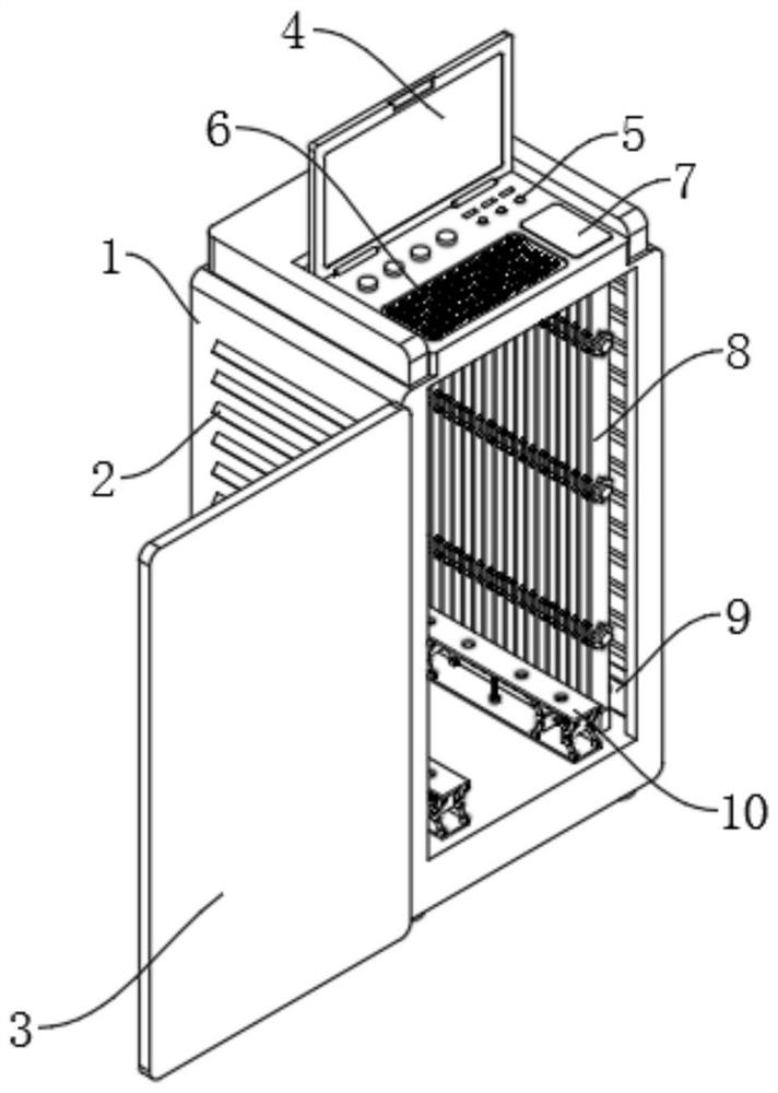
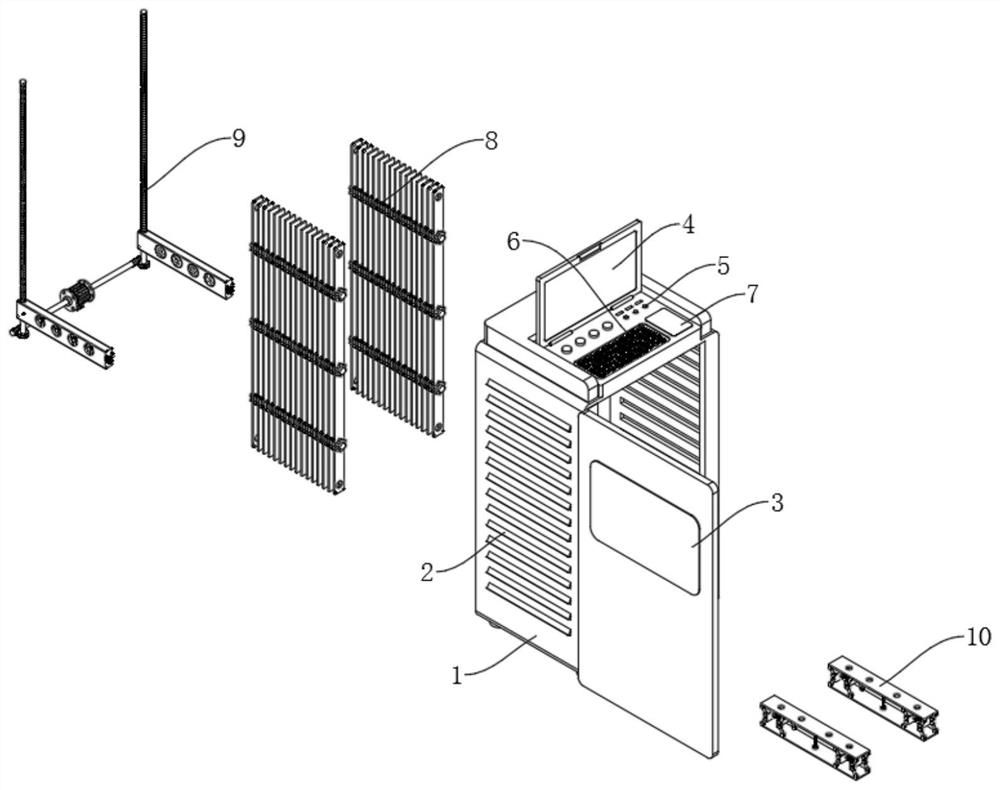
[0037] See Figure 1-3 , A computer control device and control method for product processing equipment, including an installation cabinet 1, a heat dissipation grille 2, and a cabinet door 3. The four corners of the bottom surface of the installation cabinet 1 are fixedly connected with non-slip support feet, and the heat dissipation grille 2 is set in the installation cabinet. On the side wall of 1, the vertical edge of the installation cabinet 1 is fixedly installed with hinges, the cabinet door 3 is movably connected to the installation cabinet 1 through the hinges, and the top of the installation cabinet 1 is rotatably connected with the display screen 4, and the installation cabinet 1 The interface module 5, the control input module 6 and the touch panel 7 are also fixedly installed on the top surface. The installation cabinet 1 is provided with a mounting cavity, and the side wall of the mounting cavity is connected with a heat-absorbing and dust-proof mechanism 8 to absorb...

Embodiment 2

[0041] See Figure 4-6 , Combined with the basis of embodiment 1, the difference is that the movable heat sink 9 includes a reciprocating drive mechanism, the reciprocating drive mechanism includes a dual-axis servo motor 901, and the output shaft of the dual-axis servo motor 901 is fixedly connected with a transmission shaft 902 The end of the transmission rod 902 away from the single-axis servo unit 901 is fixedly connected with a worm 903. The worm 903 is meshed and connected with the worm wheel 904. The worm wheel 904 is fixedly connected to the double-threaded reciprocating drive rod 905. .

[0042] The movable heat sink 9 also includes a heat dissipation mechanism. The heat dissipation mechanism includes a mounting shell 907, which is fixedly connected to the connecting block 906, a mounting frame 908 is fixedly connected to the mounting shell 907, and a cooling fan is fixedly mounted on the mounting frame 908, A dust-proof filter 909 is fixedly connected to the inner side...

Embodiment 3

[0046] See Figure 7 The difference between the foundation of embodiment 1 or 2 is that the shock-absorbing installation mechanism 10 includes a mounting bottom plate 1001 and a mounting top plate 1002. The mounting bottom plate 1001 is fixedly connected to the mounting plate, and the mounting top plate 1002 is provided with a mounting hole 1003. , The mounting bottom plate 1001 and the mounting top plate 1002 are rotatably connected with a mounting link 1004, the mounting link 1004 is also rotatably connected to the mounting block 1005, the first shock-absorbing spring 1006 is fixedly connected between the mounting blocks 1005, the mounting bottom 1001 and the mounting A second shock-absorbing spring 1007 is fixedly connected between the top plates 1002.

[0047] The mounting top plate 1002 of the shock-absorbing installation mechanism 10 of the present invention is provided with a mounting hole 1003. The computer equipment used to control product processing can be fixedly instal...


PUM


Abstract

The invention discloses a computer control device and control method of product machining equipment, and belongs to the technical field of control devices. The computer control device and control method of product processing equipment comprise a mounting cabinet body, a cabinet door, a safety lock and a heat dissipation grid. The bottom surface of the mounting cabinet body is fixedly connected with antiskid supporting legs. Hinges are fixedly mounted on a vertical edge of the mounting cabinet body, and the cabinet door is movably connected to the mounting cabinet body through the hinges. The safety lock is fixedly mounted at the end, far away from the hinges, of the cabinet door, and the safety lock is also fixedly connected with a handle. The heat dissipation grid is fixedly connected tothe side wall of the mounting cabinet body. A mounting plate is fixedly connected to the bottom end of the interior of the mounting cabinet body, and a fixed mounting frame is fixedly connected to themounting plate. Clamping blocks are fixedly connected to the inner top face of the mounting cabinet body and the mounting plate, and a heat absorption mechanism is further installed in the mounting cabinet body. The problem that an existing design is simple in heat dissipation structure and poor in heat dissipation effect is effectively solved.

Description

Technical field [0001] The invention relates to the technical field of control devices, in particular to a computer control device and a control method for product processing equipment. Background technique [0002] Computer control technology is based on electronic technology, automatic control technology, and computer application technology, with computer control technology as the core, integrated programmable control technology, single-chip technology, and computer network technology, so as to realize the precision of production technology and production equipment With the rapid development of technology and Internet technology, computerized control technology has become more and more widely used in our lives. [0003] With the development of computer control technology, people are beginning to use it in industrial production more and more. In view of this, it is very necessary to design a computer control device and control method for product processing equipment. As we all kno...

Claims


Application Information

Patent Timeline
Patent Type & Authority Applications(China)
IPC IPC(8): G06F1/20
CPCG06F1/20
Inventor 车林张游浩王纯达
Owner YANTAI ENG & TECH COLLEGE YANTAI TECHNICIAN INST
Why Eureka
Try Eureka