A kind of abandoned glass glue pipe treatment equipment

A technology of waste glass and processing equipment, which is applied in the direction of plastic recycling and recycling technology, can solve the problems of time-consuming, labor-intensive, low processing efficiency, etc., and achieve the effect of improving processing efficiency and preventing stagnation

Active Publication Date: 2022-08-05
东营正兴石油装备有限公司
View PDF16 Cites 0 Cited by
  • Summary
  • Abstract
  • Description
  • Claims
  • Application Information

AI Technical Summary

Problems solved by technology

[0006] In order to overcome the time-consuming and labor-intensive and low-efficiency disadvantages of cutting off the mouth and the bottom of the discarded glass glue plastic tube with a manual hand-held cutter, the technical problem to be solved by the invention is to provide a method that can save time and effort, improve Waste glass hose processing equipment with high processing efficiency

Method used


Image

  • A kind of abandoned glass glue pipe treatment equipment
  • A kind of abandoned glass glue pipe treatment equipment
  • A kind of abandoned glass glue pipe treatment equipment

Examples


Embodiment 1

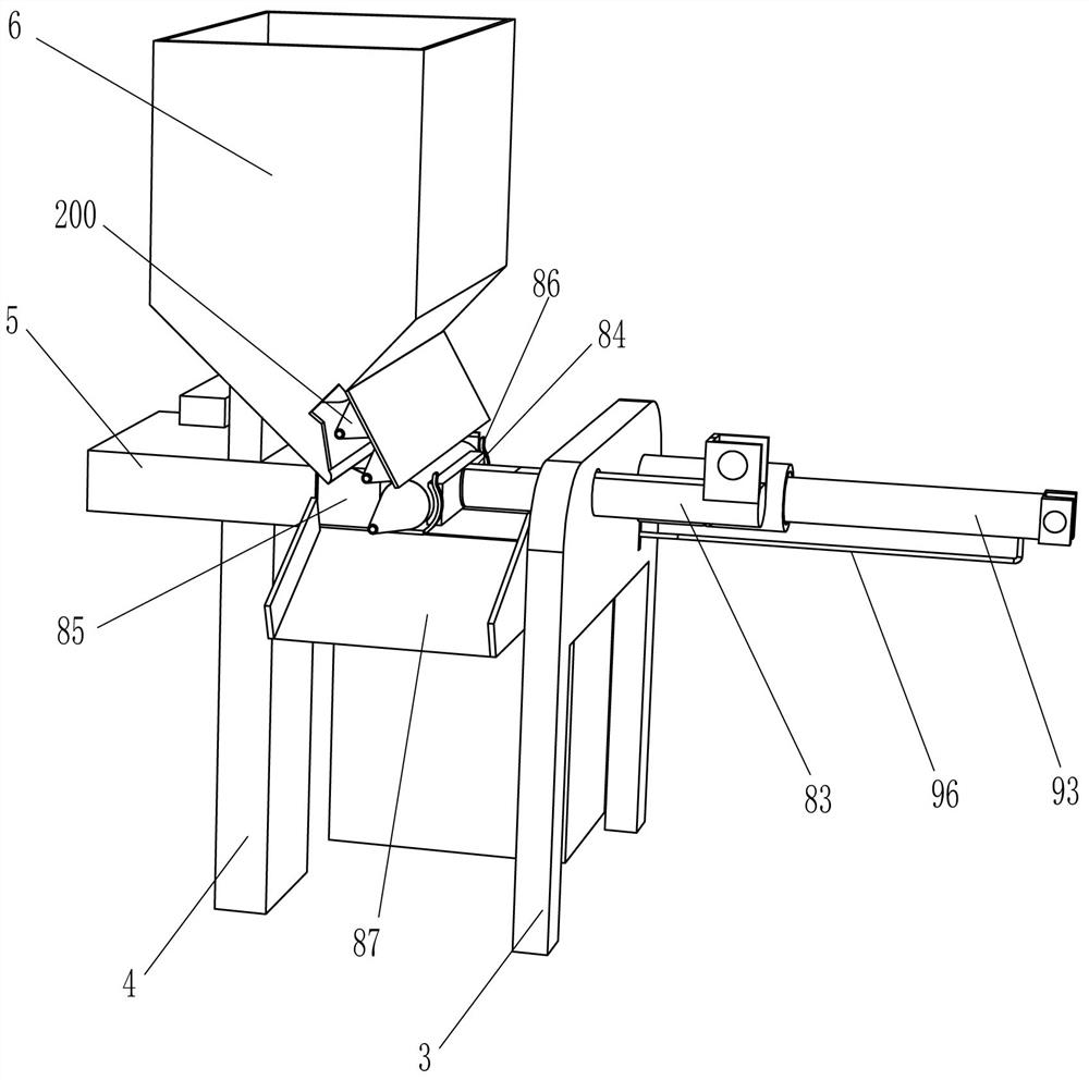
[0030] A waste glass hose treatment equipment, such as Figure 1-7 As shown, it includes a base 1, an installation frame 2, a guide frame 3 and a support frame 4, and also includes a guide frame 5, a blanking frame 6, a driving mechanism 7, an end cutting mechanism 8 and a material extrusion device 9. A mounting frame 2 is connected to the left side of the top, a guide frame 3 is connected to the top right side of the base 1, a support frame 4 is connected to the top of the base 1 on the right side of the guide frame 3, and a guide frame 5 is embedded in the upper part of the support frame 4 to guide the The inner bottom of the frame 5 is inclined to the left and the right bottom. The top of the support frame 4 is connected with a blanking frame 6, and the blanking frame 6 is communicated with the guide frame 5. A drive mechanism 7 is installed on the mounting frame 2. An end cutting mechanism 8 and an extruding device 9 are installed, the driving mechanism 7 is drivingly conn...

Embodiment 2

[0036] On the basis of Example 1, as figure 1 , figure 2 , image 3 and Figure 8 As shown, it also includes a gift-giving mechanism 10. The gift-giving mechanism 10 includes a quarter-tooth missing gear 101, a rotating rod 102, a full-tooth gear 103, a belt drive assembly 104, a fixed frame 105, a drive shaft 106, a turntable 107, a positioning The bar 108, the connecting frame 109 and the cone-head motorized roller 110, the drive shaft 72 on the lower side of the three-quarter missing toothed disc 73 is connected with a quarter missing tooth gear 101, and the right side of the mounting frame 2 is connected in a rotary manner There is a rotating rod 102, the top of the rotating rod 102 is connected with a full-tooth gear 103, the full-tooth gear 103 meshes with the quarter-tooth missing gear 101, the top of the base 1 on the right side of the support frame 4 is connected with a fixed frame 105, and the fixed frame 105 A transmission shaft 106 is rotatably connected to the...

Embodiment 3

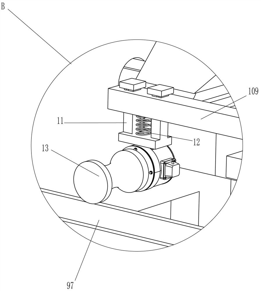
[0039] On the basis of Example 2, as Figure 9 As shown, it also includes a sliding frame 11, a compression spring 12 and a feeding roller 13, the top left side of the connecting frame 109 is vertically slidably connected with the sliding frame 11, the sliding frame 11 penetrates the connecting frame 109, and the inner top of the sliding frame 11 is connected There is a compression spring 12 , the top of the compression spring 12 is connected with the bottom of the connecting frame 109 , and the bottom of the sliding frame 11 is connected with the feeding roller 13 .

[0040] The compression spring 12 can make the feeding roller 13 closely adhere to the waste glass glue plastic tube 200 after the bottle mouth is cut off on the semi-circular tube 97. Manually start the feeding roller 13 to make the feeding roller 13 rotate clockwise, and the feeding roller 13 rotates clockwise and the cone head The cooperation of the electric roller 110 can smoothly move the waste glass glue pl...


PUM


Abstract

The invention relates to a glass rubber tube processing device, in particular to a waste glass rubber tube processing device. The technical problem to be solved by the present invention is how to provide a waste glass rubber tube processing equipment that can save time and effort and improve processing efficiency. In order to solve the above technical problems, the present invention provides such a waste glass rubber hose processing equipment, comprising: a base, the end of which is connected with an installation frame, the end of the base away from the installation frame is connected with a guide frame, and the end of the base close to the guide frame A support frame is connected; the guide frame, the upper part of the support frame is installed with a guide frame, the inner bottom of the guide frame is inclined, the top of the support frame is connected with a blanking frame, and the blanking frame is communicated with the guide frame; the driving mechanism, the installation frame A drive mechanism is installed on it. The push plate of the present invention moves to the right to push the waste glass glue plastic tube to move to the right, and under the action of the cutter, the bottle mouth of the waste glass glue plastic tube can be cut off.

Description

technical field [0001] The invention relates to a glass rubber tube processing device, in particular to a waste glass rubber tube processing device. Background technique [0002] Glass glue, a commonly used adhesive in households, is composed of sodium silicate and acetic acid and organic silicone. Sodium silicate is easily soluble in water and is viscous. It is called water glass in the south and Paohua alkali in the north. [0003] At present, the production factory generally pours the glass glue into the glass glue plastic tube for easy storage and use, and the used glass glue plastic tube is discarded. In order to prevent waste and save resources, it is necessary to recycle the discarded glass glue plastic tube. Since glass glue is generally still left in the waste glass glue plastic tube, it is necessary to remove the residual glass glue in the waste glass glue plastic tube before recycling the waste glass glue plastic tube. Since the waste glass glue plastic tube is s...

Claims


Application Information

Patent Timeline
Patent Type & Authority Patents(China)
IPC IPC(8): B29B17/00
CPCB29B17/00B29B2017/001Y02W30/62
Inventor 周国星
Owner 东营正兴石油装备有限公司
Why Eureka
Try Eureka