Method and device for detecting water consumption of equipment and cleaning equipment
A detection device and detection method technology are applied in the field of devices, cleaning equipment, and detection methods for water consumption of equipment, and can solve problems such as poor working effect of equipment.
- Summary
- Abstract
- Description
- Claims
- Application Information
AI Technical Summary
Problems solved by technology
Method used
Image
Examples
Embodiment 1
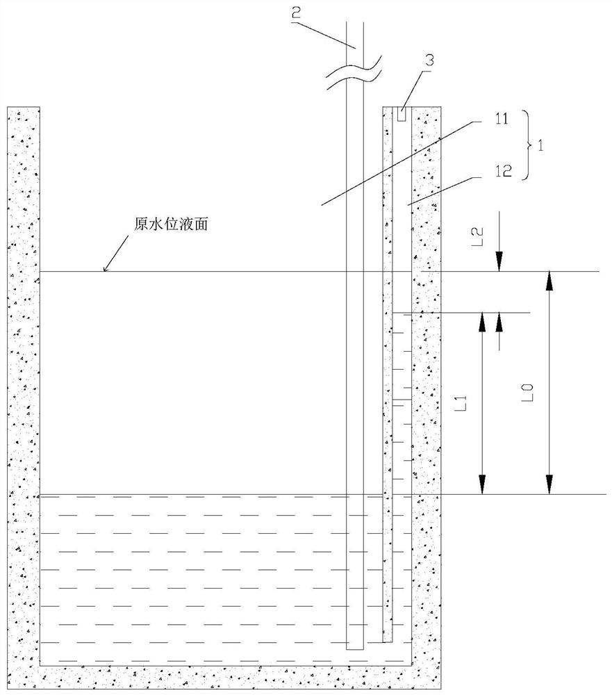
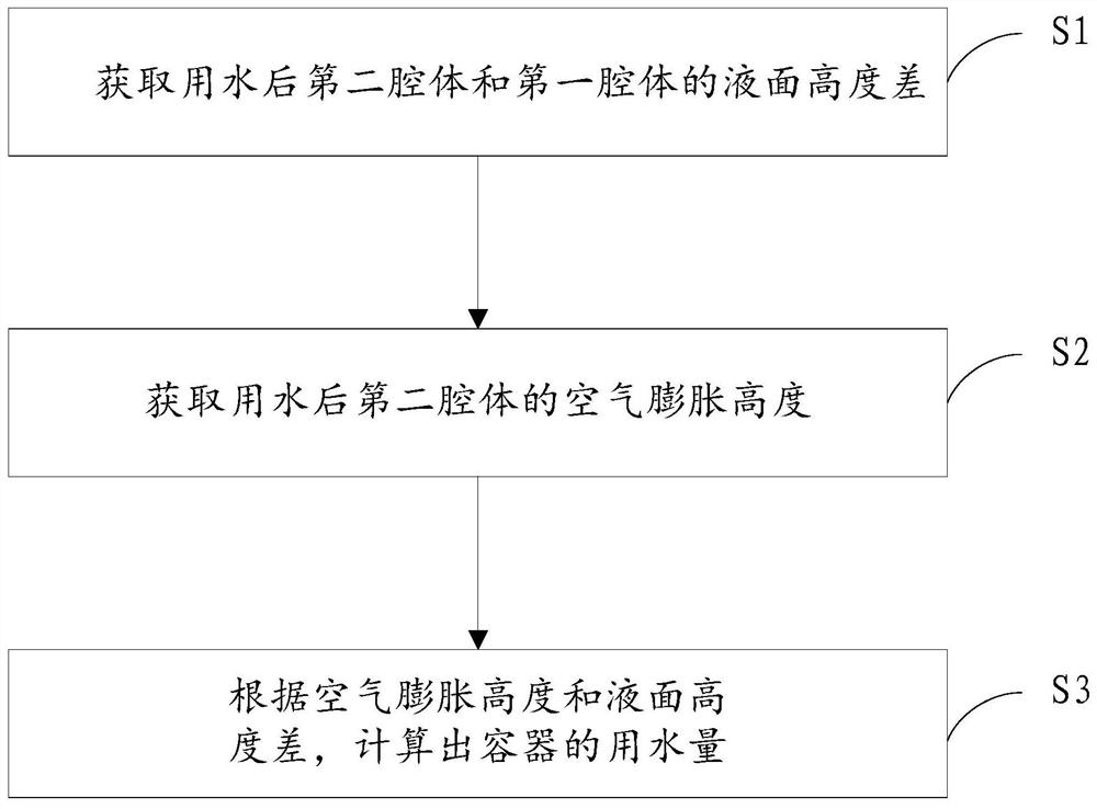
[0062] See Figure 1-2, Embodiments of the present invention provides a method of detecting water apparatus for the second cavity 11 and the detector 12 water reservoir, within the reservoir 11 comprises a horizontal laying and communicating with the first cavity, the first cavity 11 is provided for pumping the suction pipe 2, the top of the second cavity 12 is provided with an opening (not shown) and a sealing cap (not shown), the lid closing the opening when water seal cover opening the opening, after filling, capping an opening sealing cover. Water before, the sealing cap may be opened when filled with water from the opening, so that the first cavity 11 and second cavity 12 are in communication with the atmospheric state, to ensure that liquid of the first cavity 11 and second cavity 12 highly uniform surface, and the second cavity 12 above the liquid level of the air pressure are atmospheric pressure while the first cavity 11, after filled with water, then with a sealing cap ca...
Embodiment 2
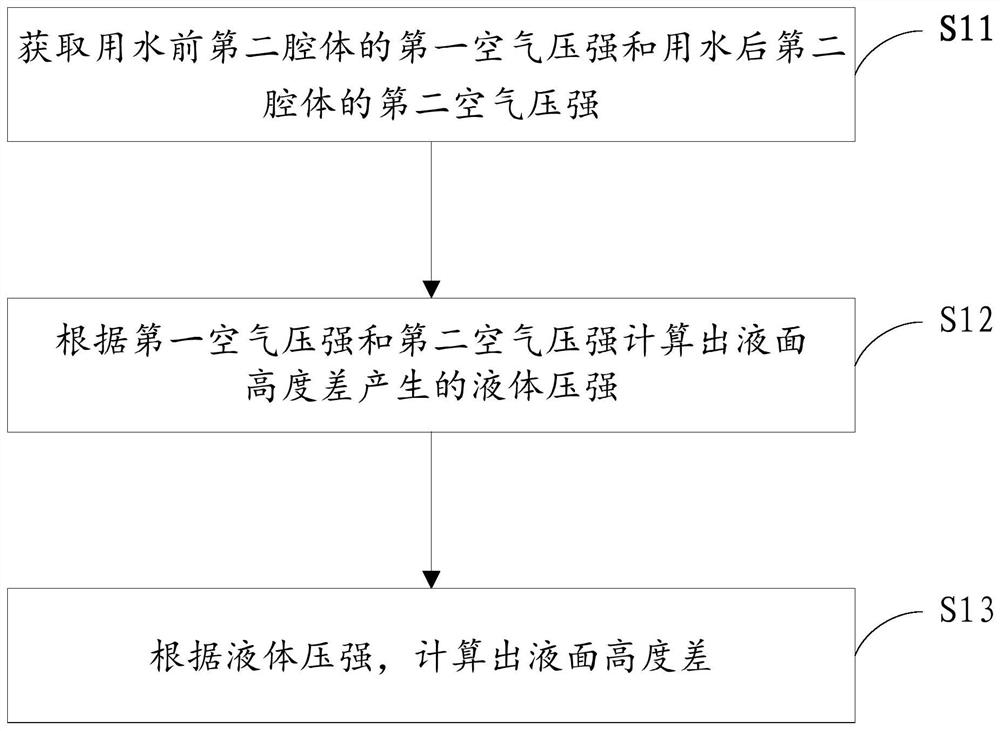
[0073] See image 3 The first cavity 11 and the liquid surface height difference of water after obtaining the second chamber 12 includes the following steps: Further, the step S1:
[0074] S11: obtaining a second water prior to the second cavity after the first air chamber 12 and the water pressure P0 of the second air pressure P1 body 12;
[0075] Water before, a first cavity 11 and second cavity 12 of the liquid level height, where this second chamber 12 inside the first air tertiary air above the liquid level and the pressure P0 above the first cavity body 11 the same pressure, atmospheric pressure are, the second air pressure P1 detected by the following means can be a pressure sensor 12 are installed at the top of the body 3 is directly read in the second chamber;
[0076] S12: The first air pressure and second air pressure P0 P1, the calculated surface height difference of the liquid pressure P2 L1 generated;
[0077] The liquid level height difference between the pressure P2...
Embodiment 3
[0081] See Figure 4 , Further, step S2: the expansion of air acquires water after the second cavity 12 height comprises the steps of:
[0082] S21: obtaining the air volume V0 12 with water before the second cavity;
[0083] Air volume V0 can body 12 according to the second chamber cross-sectional area S 'and the height of the second air chamber 12 with water prior to obtaining L3, L3 is the height of the air known parameters;
[0084] S22: The air volume V0, the first air pressure P0, the second air pressure P1, to calculate the water after the second air chamber 12 of expanded volume Vl;
[0085] Since the second cavity 12 is provided to seal the air content in the second cavity 12 are the same before and after the water and water, according to equation Krabbe Long:
[0086] P0V0 = (m / M) RT, P1 (V0 + V1) = (m / M) RT, where, m is the mass of gas, M being the molar mass of the gas, R is the universal gas constant, T is the gas temperature, in application of the embodiment of th...
PUM
 Abstract
Description
Claims
Application Information
 - R&D
- Intellectual Property
- Life Sciences
- Materials
- Tech Scout
- Unparalleled Data Quality
- Higher Quality Content
- 60% Fewer Hallucinations
Browse by: Latest US Patents, China's latest patents, Technical Efficacy Thesaurus, Application Domain, Technology Topic, Popular Technical Reports.
© 2025 PatSnap. All rights reserved.Legal|Privacy policy|Modern Slavery Act Transparency Statement|Sitemap|About US| Contact US: help@patsnap.com


