
a mist remover

A technology of oil collection tank and cyclone separator, which is applied in the direction of chemical instruments and methods, dispersed particle separation, combined devices, etc., which can solve the problems of inconvenient operation of degreasing mist and the inability to remove oil slicks in real time, and achieve the effect of reducing viscosity

Inactive Publication Date: 2016-01-13
宁波新芝华东环保科技有限公司
View PDF7 Cites 0 Cited by
  • Summary
  • Abstract
  • Description
  • Claims
  • Application Information

AI Technical Summary

Problems solved by technology

The working process of the degreasing mist device is as follows: first, put an appropriate amount of water in the water tank, input the exhaust gas discharged from the equipment into the air intake mechanism, and the water spray mechanism sprays water droplets at the air inlet of the air intake mechanism after the water spray mechanism is connected to the water source. After being mixed with water, it is input into the cyclone separator through the air inlet mechanism, and the mixture of tail gas and water realizes oil and gas separation under the action of the cyclone separator, and the separated gas is output through the output end of the cyclone separator, and the separated oily water is The inner wall of the cyclone separator sinks into the water tank and mixes with the water in the water tank. Because the density of oil is lower than that of water, the oil particles will gradually separate from the water under their own gravity and float on the water surface to form a layer of oil slick. When the oil slick After accumulating to a certain thickness, the equipment management personnel opened the water tank to fish out the floating oil, which made it inconvenient to operate the oil mist eliminator and could not remove the floating oil in real time

Method used


Image

  • a mist remover
  • a mist remover

Examples


Embodiment 1

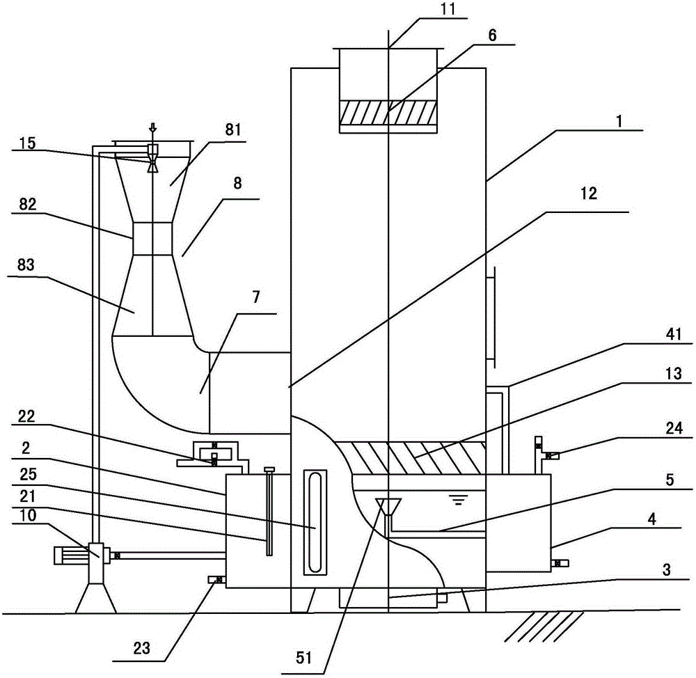
[0018] Embodiment one: if figure 1 Shown, a kind of degreasing mist device comprises cyclone separator 1, air intake mechanism, the water spray mechanism and water tank 2 that are used to spray water at the air inlet place of air intake mechanism, and water tank 2 is positioned at cyclone separator 1 below and It communicates with the bottom of the cyclone separator 1, the cyclone separator 1 is provided with an oil discharge mechanism, the bottom of the water tank 2 is provided with an ultrasonic emission unit 3 that transmits ultrasonic waves to the inside of the water tank 2, and the oil discharge mechanism includes an oil collection tank 4 and a first pipeline 5, The first pipeline 5 communicates with the water tank 2 and the oil collection tank 4. The port 51 of the first pipeline 5 located in the water tank 2 is an oil inlet. The oil tank 4 and the cyclone separator 1 are connected through a pipeline 41 to ensure that the air pressure in the two is the same, so that the ...

Embodiment 2

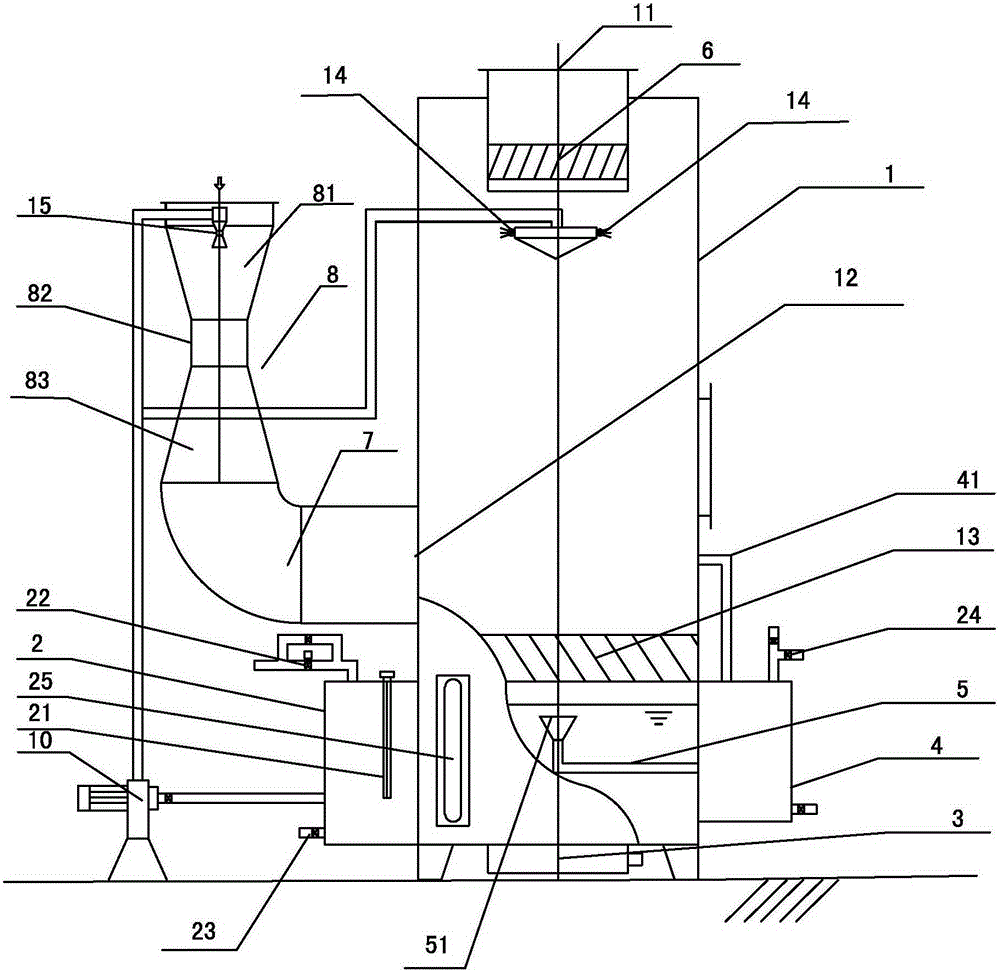
[0024] Embodiment two: if figure 2 As shown, the present embodiment is provided with a plurality of nozzles 14 in a circle in the cyclone separator 1 on the basis of Embodiment 1, and the plurality of nozzles 14 are respectively connected to the output end of the high-pressure water pump 10, and the plurality of nozzles 10 are set At the output 11 close to the cyclone 1 .


PUM


Abstract

The invention discloses an oil demister, comprising a cyclone separator, an intake mechanism, a spraying mechanism and a water tank, wherein the water tank is arranged below the cyclone separator and communicated with the cyclone separator; an oil discharge mechanism is arranged outside the cyclone separator; an ultrasonic emission unit for emitting an ultrasonic wave to the internal part of the water tank is arranged at the bottom of the water tank; the oil discharge mechanism comprises an oil collection tank and a first pipeline; the first pipeline is communicated with the water tank and the oil collection tank; the port of the first pipeline inside the water tank is an oil inlet; the oil inlet of the first pipeline is horizontally arranged and 2-3cm higher than the water level inside the water tank; the oil collection tank is communicated with the cyclone separator; the demister is arranged at the output end of the cyclone separator; the intake mechanism comprises a venturi tube and a second pipeline; an air inlet of the intake mechanism is formed at one end of the venturi tube; an air outlet of the intake mechanism is formed at the other end of the venturi tube; the other end of the venturi tube is communicated with the cyclone separator through a second pipeline. The oil demister has the advantages of being convenient to operate, realizing real-time cleaning of oil slick on the water surface, and achieving the oil mist removal efficiency of up to 95%.

Description

technical field [0001] The invention relates to exhaust gas purification equipment, in particular to an oil mist remover. Background technique [0002] With the rapid development of industrial technology, industrial production has gradually realized automation, and various automation equipment are inevitably used in the automation process of industrial production. The exhaust gas produced by automation equipment usually contains oil mist. If the exhaust gas is directly discharged into the air, it will pollute the environment. In order to prevent the exhaust gas from polluting the environment, the exhaust gas is generally treated by an oil mist remover, and the oil mist in the exhaust gas is separated to obtain a purified gas output. [0003] Existing degreasing mist generally comprises air intake mechanism, water spray mechanism, cyclone separator and water tank, and water spray mechanism is used for spraying water at the air inlet place of air intake mechanism to mix tail ...

Claims


Application Information

Patent Timeline
Patent Type & Authority Patents(China)
IPC IPC(8): B01D50/00
Inventor 林小平
Owner 宁波新芝华东环保科技有限公司
Learn More