Optical system, camera module and electronic equipment

An optical system, optical axis technology, applied in optics, optical components, instruments, etc., can solve problems such as unsatisfactory focal length and total length of the system

Pending Publication Date: 2020-11-06
JIANGXI JINGCHAO OPTICAL CO LTD
View PDF0 Cites 6 Cited by
  • Summary
  • Abstract
  • Description
  • Claims
  • Application Information

AI Technical Summary

Problems solved by technology

[0003] The current seven-chip optical system is limited by the size of the multi-camera electronic device. The total length of the system i

Method used


Image

  • Optical system, camera module and electronic equipment
  • Optical system, camera module and electronic equipment
  • Optical system, camera module and electronic equipment

Examples


no. 1 example

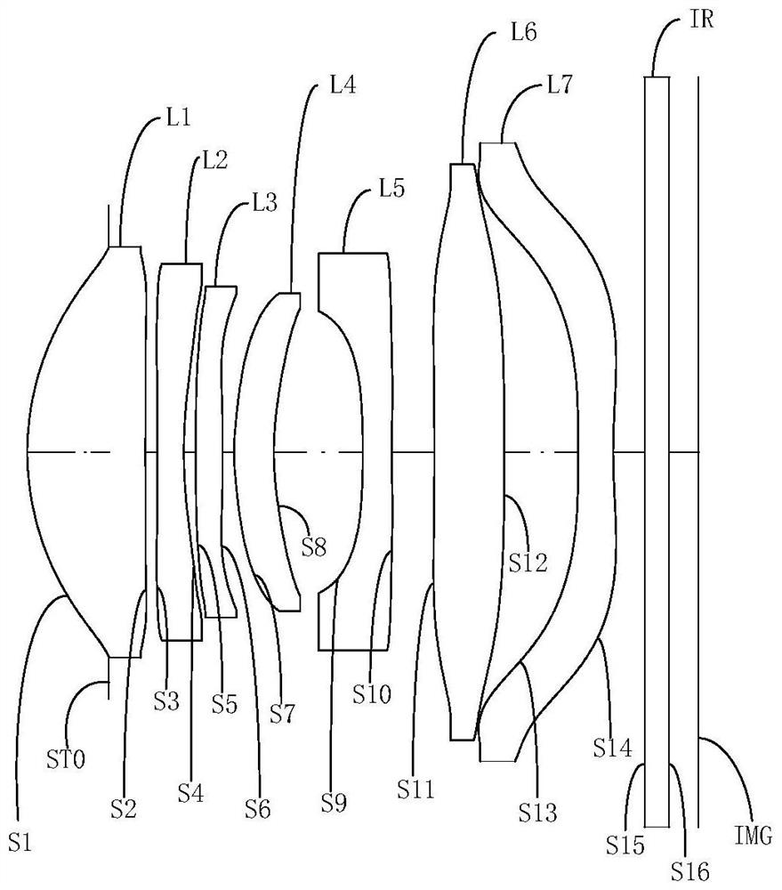
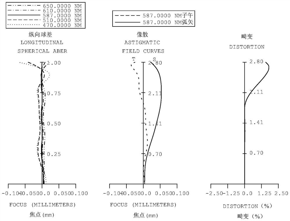
[0055] Please refer to Figure 1a with Figure 1b , the optical system of this embodiment includes in sequence from the object side to the image side along the optical axis direction:

[0056] The first lens L1 has positive refractive power. The object side S1 of the first lens L1 is convex at the near optical axis and at the circumference; the image side S2 of the first lens L1 is concave at the near optical axis and at the circumference. is convex;

[0057] The second lens L2 has negative refractive power. The object side S3 of the second lens L2 is convex at the near optical axis and at the circumference; the image side S4 of the second lens L2 is convex at the near optical axis and at the circumference. concave surface

[0058] The third lens L3 has a negative refractive power. The object side S5 of the third lens L3 is convex at the near optical axis and concave at the circumference; the image side S6 of the third lens L3 is equal at the near optical axis and at the cir...

no. 2 example

[0076] Please refer to Figure 2a with Figure 2b , the optical system of this embodiment includes in sequence from the object side to the image side along the optical axis direction:

[0077] The first lens L1 has positive refractive power. The object side S1 of the first lens L1 is convex at the near optical axis and at the circumference; the image side S2 of the first lens L1 is concave at the near optical axis and at the circumference. is convex;

[0078] The second lens L2 has negative refractive power. The object side S3 of the second lens L2 is convex at the near optical axis and at the circumference; the image side S4 of the second lens L2 is convex at the near optical axis and at the circumference. concave surface

[0079] The third lens L3 has a negative refractive power. The object side S5 of the third lens L3 is convex at the near optical axis and at the circumference; the image side S6 of the third lens L3 is convex at the near optical axis and at the circumfer...

no. 3 example

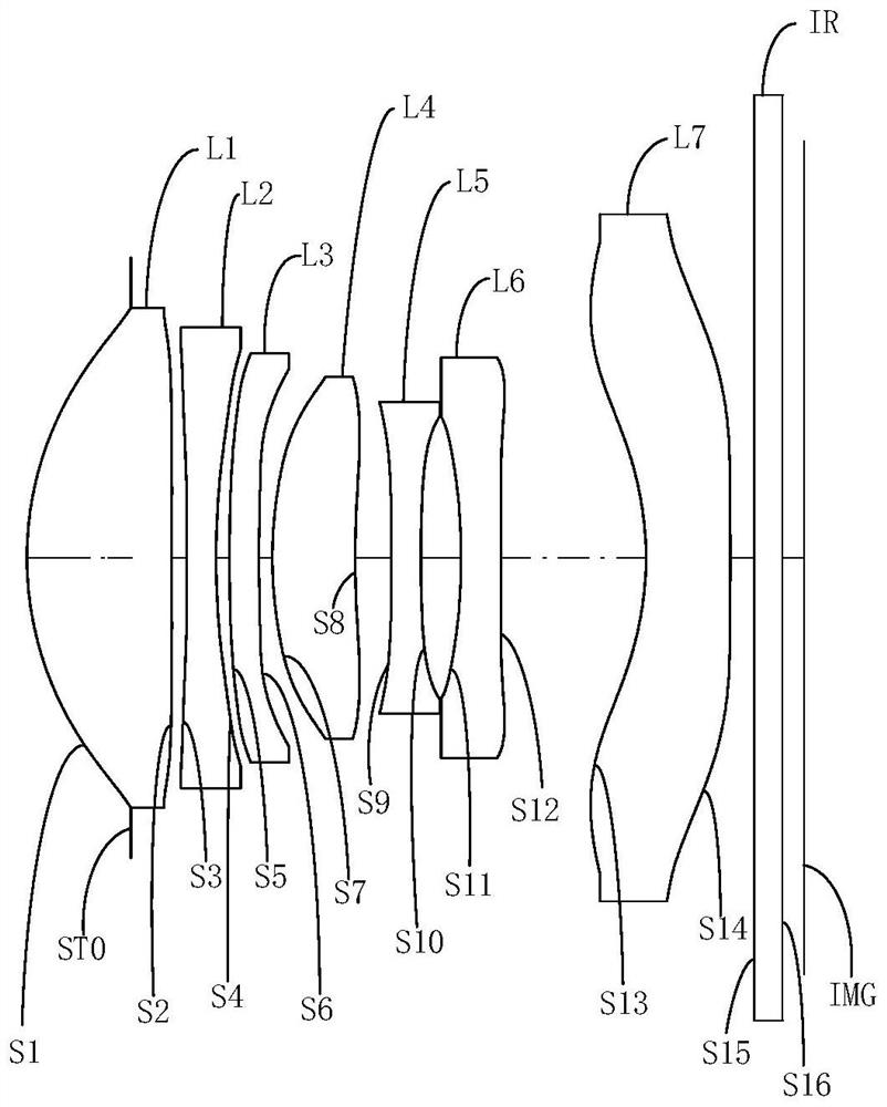
[0096] Please refer to Figure 3a with Figure 3b , the optical system of this embodiment includes in sequence from the object side to the image side along the optical axis direction:

[0097] The first lens L1 has positive refractive power. The object side S1 of the first lens L1 is convex at the near optical axis and at the circumference; the image side S2 of the first lens L1 is concave at the near optical axis and at the circumference. is convex;

[0098] The second lens L2 has negative refractive power. The object side S3 of the second lens L2 is convex at the near optical axis and at the circumference; the image side S4 of the second lens L2 is convex at the near optical axis and at the circumference. concave surface

[0099] The third lens L3 has negative refractive power. The object side S5 of the third lens L3 is convex at the near optical axis and at the circumference; the image side S6 of the third lens L3 is concave at the near optical axis and at the circumfere...


PUM


Abstract

The invention provides an optical system, a camera module and electronic equipment. In order from an object side to an image side, the optical system comprises a first lens with positive refractive power, a convex object-side surface at a paraxial region, a concave image-side surface at the paraxial region, and a convex image-side surface at a circumferential region, a second lens with negative refractive power, a convex object-side surface at a paraxial region and a concave image-side surface at the paraxial region, a third lens and a fourth lens with refractive power, a fifth lens with refractive power and a concave object-side surface in the circumferential direction, and a sixth lens with refractive power, and at least one inflection point is arranged on at least one of the object-sidesurface and the image-side surface of the sixth lens; the optical system further comprises a seventh lens with negative refractive power and an image-side surface being convex in the circumferentialdirection, and at least one of the object-side surface and the image-side surface is provided with an inflection point. The surface types and refractive power of the first to seventh lenses are reasonably configured, and the total length of the optical system can be relatively short on the premise of not sacrificing the focal length, so that the design requirements of miniaturization and clear long-range shooting are met.

Description

technical field [0001] The invention belongs to the field of optical imaging, and in particular relates to an optical system, a camera module with the optical system and electronic equipment. Background technique [0002] Nowadays, with the rapid development of multi-camera electronic equipment, consumers have higher and higher requirements for the imaging quality of multi-camera electronic equipment, and the telephoto lens is an important part of multi-camera electronic equipment to achieve telephoto photography. It goes without saying. The telephoto lens can make objects with a distant object distance clearly imaged on the image plane, and obtain a shooting effect similar to that of a close object distance, thereby achieving the effect of space compression. [0003] The current seven-chip optical system is limited by the size of the multi-camera electronic device. The total length of the system is too long when the focal length is sufficient, or the focal length is not id...

Claims


Application Information

Patent Timeline
IPC IPC(8): G02B13/00G02B13/18
CPCG02B13/0045G02B13/18
Inventor 党绪文刘彬彬杨健李明邹海荣
Owner JIANGXI JINGCHAO OPTICAL CO LTD
Why Eureka
Try Eureka