Thin fastener of heat sink

a technology of heat sinks and fasteners, which is applied in the direction of indirect heat exchangers, semiconductor/solid-state device details, lighting and heating apparatus, etc., can solve the problems of disadvantageous to thin-and-light computers, difficult to reduce the overall height and weight, and relatively complicated structures, etc., to reduce the overall height and weight, and efficient simplify the structure of heat sink fasteners

Inactive Publication Date: 2013-07-16
CHAUN CHOUNG TECH
View PDF12 Cites 4 Cited by
  • Summary
  • Abstract
  • Description
  • Claims
  • Application Information

AI Technical Summary

Benefits of technology

[0007]An object of the invention is to provide a thin fastener of heat sink, which can efficiently simplify the structure of heat sink fastener and reduce overall height and weight. This will be advantageous to the thin and light design of electronic devices.

Problems solved by technology

In sum, this kind of structure is relatively complicated and its overall height and weight is hard to be reduced, too.
This is very disadvantageous to the thin-and light design of computers.

Method used


Image

  • Thin fastener of heat sink
  • Thin fastener of heat sink
  • Thin fastener of heat sink

Examples


first embodiment

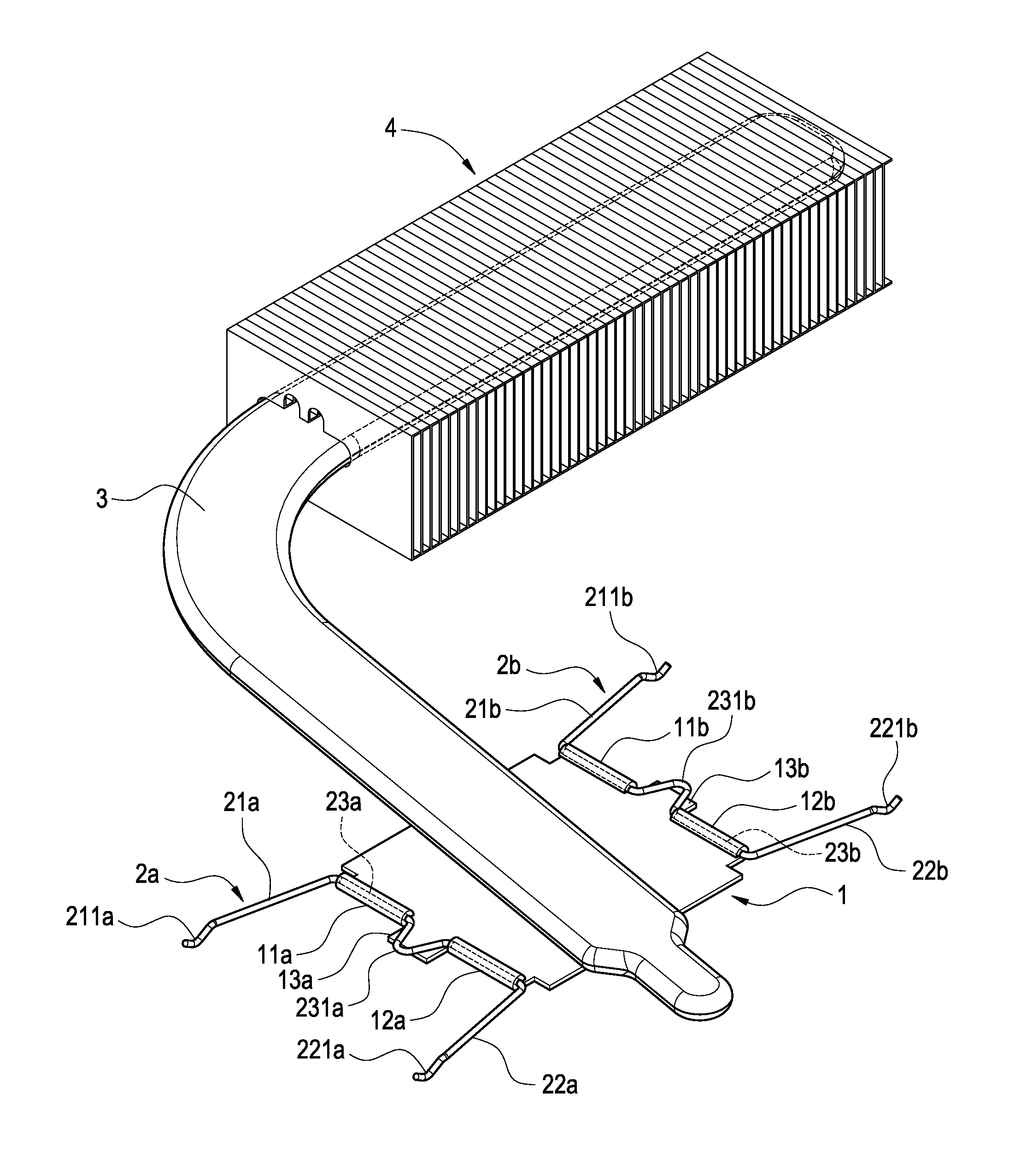
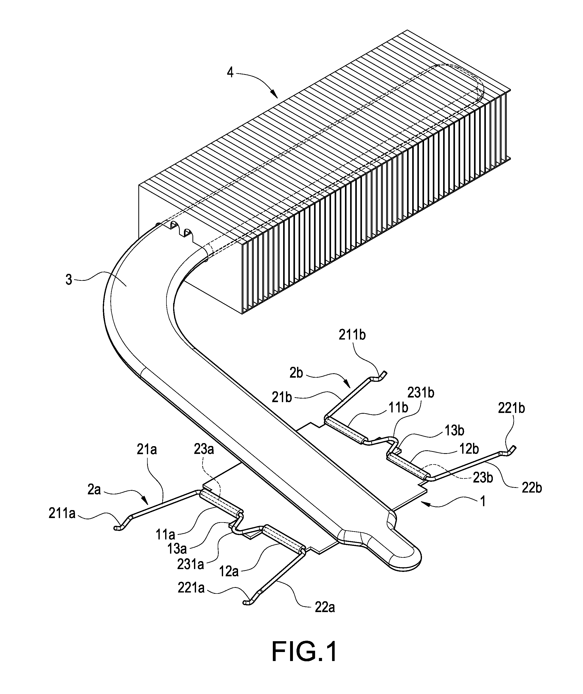
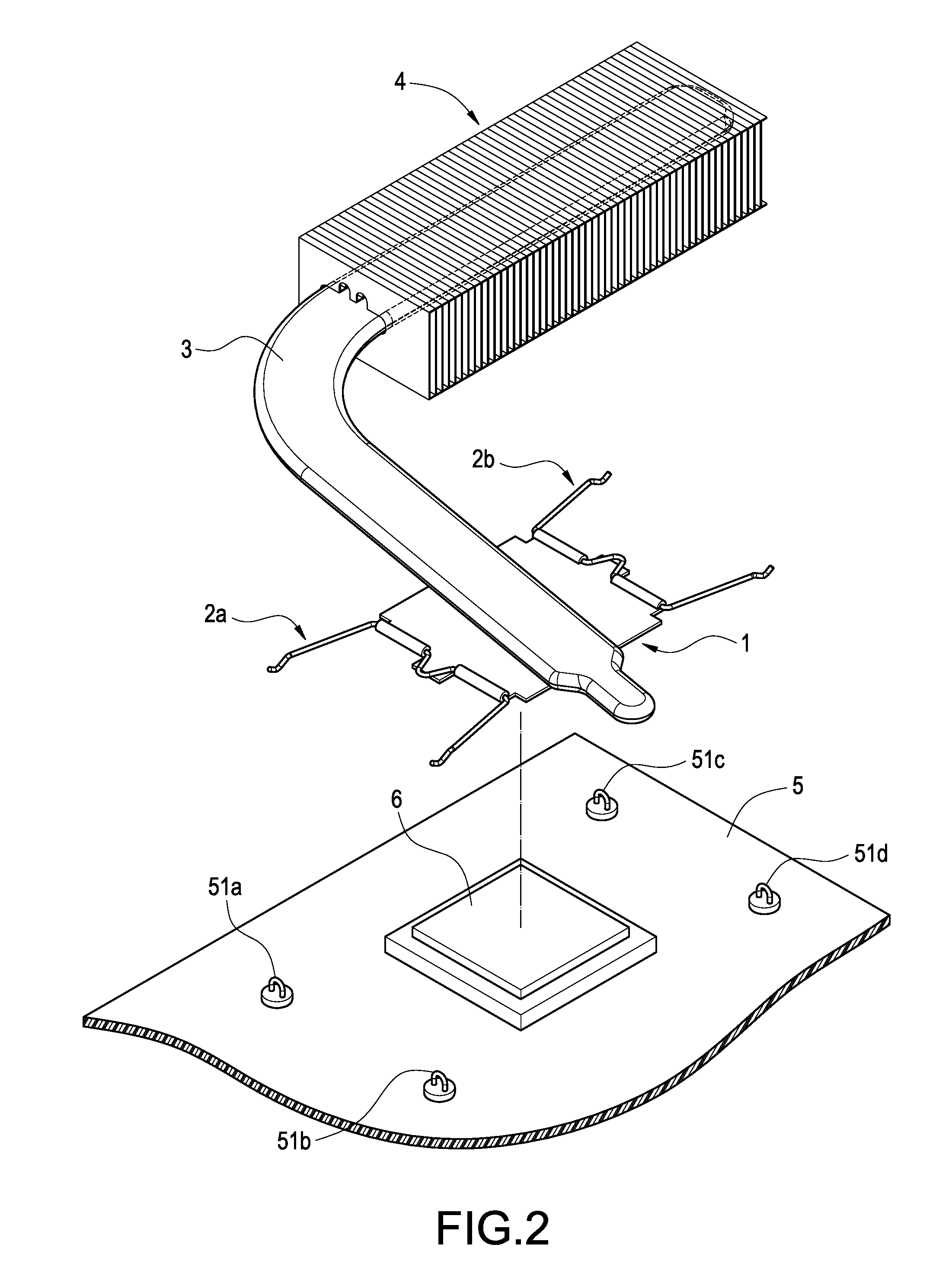
[0018]Please refer to FIG. 1, which is a perspective view of the invention. Roughly, the heat sink fastener of the invention includes a heat conductive board 1 and two flexible metallic wires 2a,2b.

[0019]Two opposite sides of the heat conductive board 1 are separately provided with two pivot portions. In this embodiment, each pivot portion is a pair of hollow cylinders 11a,12a;11b,12b. Each pair of hollow cylinders 11a,12a;11b,12b is arranged in a line and may be formed by curling an edge of the heat conductive board 1. A blocking sheet 13a,13b is formed between each pair of hollow cylinders 11a,12a;11b,12b. The blocking sheets 13a,13b are coplanar to the heat conductive board 1 and protrude from the two pairs of hollow cylinders 11a,12a;11b,12b.

[0020]Each of the two flexible metallic wires 2a,2b is of a U shape. It can be defined into a middle portion 23a,23b and two flexible arms 21a,22a;21b,22b. The middle portion 23a or 23b penetrates a pair of hollow cylinders 11a,12a or 11b,...

second embodiment

[0024]FIG. 6 shows the invention. In this embodiment, the flexible metallic wire 2c is of a U shape, which can be defined into a middle portion 23c and two flexible arms 21c,22c. The two flexible arms 21c,22c separately penetrate through two pairs of hollow cylinders 11b,12b;12b,12a. The middle portion 23c is exposed out of one side of the heat conductive board 1. The middle portion 23c and two free ends of the flexible arms 21c,22c are separately formed with hooks 211c,221c,231c for penetrating through rings as shown in the abovementioned embodiment. Similarly, the top of the heat conductive board 1 may be attached by a heat pipe 3 connecting with a fin set 4. In this embodiment, the flexible metallic wire 2c has three hooks 211c,221c,231c, so there should be three rings disposed on a circuit board (not shown) for being penetrated by the hooks 211c,221c,231c.

third embodiment

[0025]FIG. 7 shows the invention. In this embodiment, two pivot portions of the heat conductive board 1″ are separately provided with two pairs of hollow cylinders 11c,12c;11d,12d. Each pair of hollow cylinders 11c,11d;12c,12d formed by stamping and is arranged in a line. Two flexible arms 21c,22c of the flexible metallic wire separately penetrate through two pairs of hollow cylinders 11d,12d;11c,12c. Similarly, the top of the heat conductive board 1 may be attached by a heat pipe 3 connecting with a fin set 4.


PUM


Abstract

The heat sink fastener includes a heat conductive board and a flexible metallic wire. The heat conductive board has a pair of pivot portions. The flexible metallic wire has a pair of flexible arms and a middle portion connecting therebetween. Each flexible arm connects to the pivot portion. The pivot portion side of the heat conductive board is formed with a blocking sheet. The middle portion is provided with a bend for being blocked by the blocking sheet. When the flexible metallic wire is hooked to a ring on a circuit board, it will generate pressure to the heat conductive board resulting from the bent flexible arms and the blocked middle portion.

Description

BACKGROUND OF THE INVENTION[0001]1. Technical Field[0002]The invention relates to heat sinks, particularly to fasteners of heat sinks.[0003]2. Related Art[0004]With continuous improvement of semiconductor devices, the requirements to heat sinks also increase. On the other hand, electronic devices also constantly tend to be lighter, thinner, shorter and smaller. Thus heat sinks need not only to further improve to satisfy the requirements of heat dissipation of electronic devices, but also to be lighter and thinner than before.[0005]Taiwan patent No. 1305825 discloses a typical heat sink fastener of the CPU (hereinafter “TW825”). TW 825 uses a heat conductive board attached on the CPU, so the heat conductive plate must exert pressure on the CPU. In TW825, the heat conductive board is fastened by four flexible pins at corners. Each flexible pin is composed of a screw and a spring. The screws must penetrate the heat conductive board and the motherboard so as to fasten the heat conductiv...

Claims


Application Information

Patent Timeline
Patent Type & Authority Patents(United States)
IPC IPC(8): H05K7/20F28D15/00F28F7/00
CPCH01L23/4093H01L23/427F28D15/0275H01L2924/0002H01L2924/00
Inventor HUANG, MENG-CHENGTSENG, CHI-CHUNG
Owner CHAUN CHOUNG TECH
Why Eureka
Try Eureka