
Spiral curved surface wear prediction method

A technology of helical surface and prediction method, applied in special data processing applications, geometric CAD, design optimization/simulation, etc., can solve the problems of inaccurate calculation of roller screws, and achieve the effect of short research cycle and low cost

Active Publication Date: 2020-11-06
NORTHWESTERN POLYTECHNICAL UNIV
View PDF4 Cites 0 Cited by
  • Summary
  • Abstract
  • Description
  • Claims
  • Application Information

AI Technical Summary

Problems solved by technology

[0004] In order to solve the problem of inaccurate wear calculation of roller screw pair, the present invention provides a calculation method of helical surface wear

Method used


Image

  • Spiral curved surface wear prediction method
  • Spiral curved surface wear prediction method
  • Spiral curved surface wear prediction method

Examples


Embodiment Construction

[0033] Now in conjunction with embodiment, accompanying drawing, the present invention will be further described:

[0034] The invention provides a method for predicting wear of a spiral surface. During the operation of a roller screw, the wear of the spiral surface is predicted based on the Archard wear prediction method, which specifically includes the following steps:

[0035] Step 1. Establish the required coordinate system and the conversion relationship between the coordinate systems;

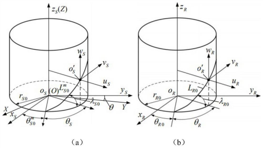
[0036] In this embodiment, the coordinate system in step 1 includes the global coordinate system, the screw fixed coordinate system, the screw section coordinate system, the roller fixed coordinate system, and the roller section coordinate system, such as figure 1 shown, and adopt the method of coordinate transformation to obtain the conversion relationship between the coordinate systems;

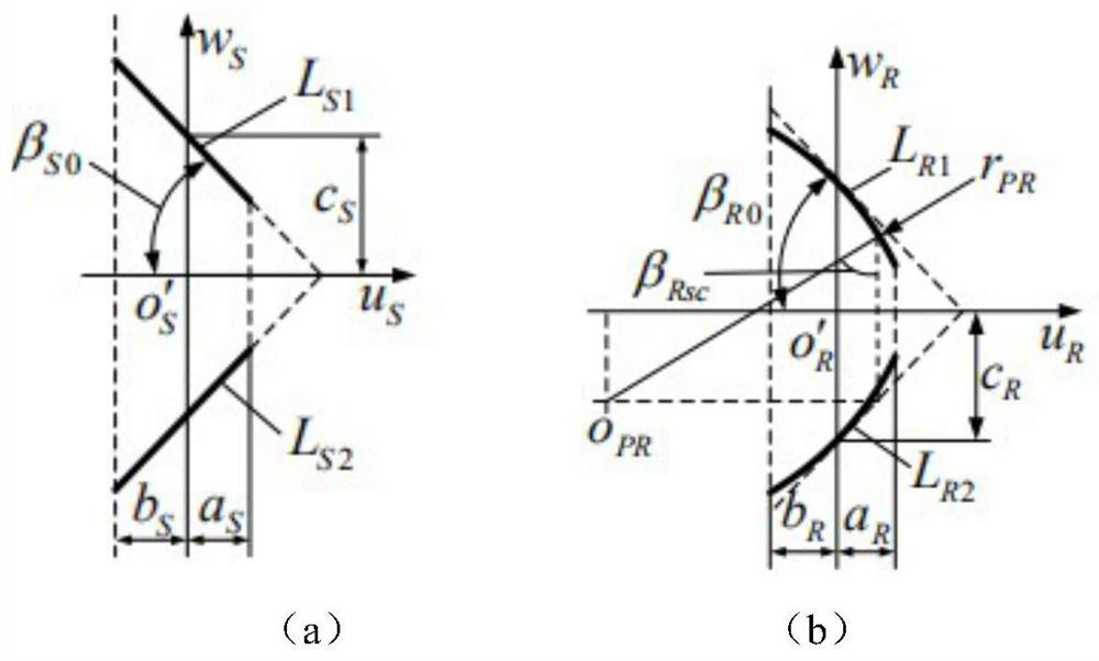
[0037] Step 2, establishing the surface equation of the screw and the roller helical surface;

[...


PUM


Abstract

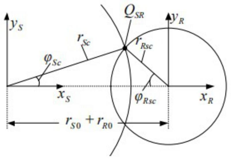
The invention relates to a spiral curved surface abrasion prediction method. On the basis of a planetary roller screw pair model, meshing motion and contact characteristics of a roller screw are analyzed, then an Archard abrasion prediction method is used for predicting abrasion of a spiral curved surface, and the method comprises the following steps of building coordinate systems of the screw anda roller respectively, and performing coordinate transformation; establishing a curved surface equation of the spiral surfaces of the lead screw and the roller; determining the position of a contactpoint of the lead screw and the roller; calculating the relative speed at the contact point; calculating the contact stress at the contact point; and based on an Archard wear prediction formula, carrying out wear prediction on the spiral curved surface.

Description

technical field [0001] The invention belongs to the technical field of wear prediction of a spiral curved surface, and more specifically relates to a method for predicting wear of a contact surface based on the movement process of a roller screw. Background technique [0002] The planetary roller screw pair is a mechanism that uses multiple rollers to engage with the helical surface between the screw and the nut to convert rotary motion into linear motion. During the movement of the roller screw pair, wear will inevitably occur. The most common form of wear is the wear of the helical surface of the roller and the screw. By predicting the wear of the helical surface, the damage of the screw can occur. Take measures in advance to ensure that the accuracy of the operation is not affected and avoid unnecessary losses. Contents of the invention [0003] technical problem to be solved [0004] In order to solve the problems of inaccurate calculation of the wear of the roller s...

Claims


Application Information

Patent Timeline
Patent Type & Authority Applications(China)
IPC IPC(8): G06F30/17G06F30/20G06F111/10
CPCG06F30/17G06F30/20G06F2111/10
Inventor 马尚君李闯闯刘更
Owner NORTHWESTERN POLYTECHNICAL UNIV
Learn More