
Signal lamp with positioning function

A technology of signal lights and functions, applied in the field of signal lights, can solve the problems of road traffic paralysis and signal lights taking a long time, and achieve the effects of saving resource investment, strong practicability and convenient operation.

Pending Publication Date: 2020-11-06
安徽信联建设工程有限公司
View PDF0 Cites 0 Cited by
  • Summary
  • Abstract
  • Description
  • Claims
  • Application Information

AI Technical Summary

Problems solved by technology

[0004] The purpose of the present invention is to provide a signal lamp with a positioning function to solve the problem that the traffic signal lamp in the prior art fails, and it takes a lot of time to temporarily deploy the signal lamp, which will lead to the problem of road traffic paralysis

Method used


Image

  • Signal lamp with positioning function
  • Signal lamp with positioning function
  • Signal lamp with positioning function

Examples


Embodiment 1

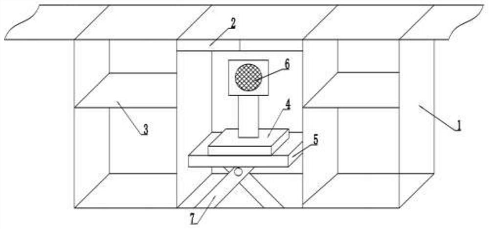
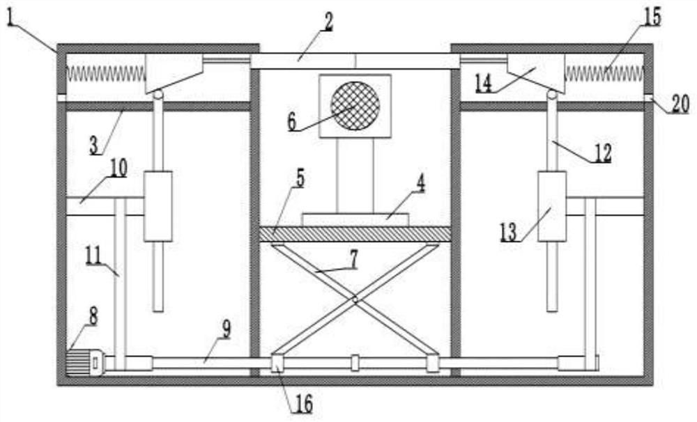
[0026] Example 1, please refer to Figure 1-2 : A signal light with positioning function, including a box body 1. There are two vertical boards fixedly installed in the box body 1. The two vertical boards divide the box body 1 into three left, middle and right chambers. There is a The box mouth is slidingly connected with two cover plates 2 made of high-quality carbon structural materials. The horizontal plates 3 are fixedly installed in the left and right chambers of the box body 1, and the left and right chambers are located in the horizontal plate 3. A telescopic mechanism for controlling the cover plate 2 is provided above. Telescoping mechanism comprises trapezoidal cam 14, and trapezoidal cam 14 is slidably connected at the top in casing 1, and is fixedly connected between trapezoidal cam 14 and cover plate 2, and is fixedly connected with spring 15 between trapezoidal cam 14 and casing 1 sidewall. The left and right chambers are connected with a rotating shaft 10 and a...

Embodiment 2

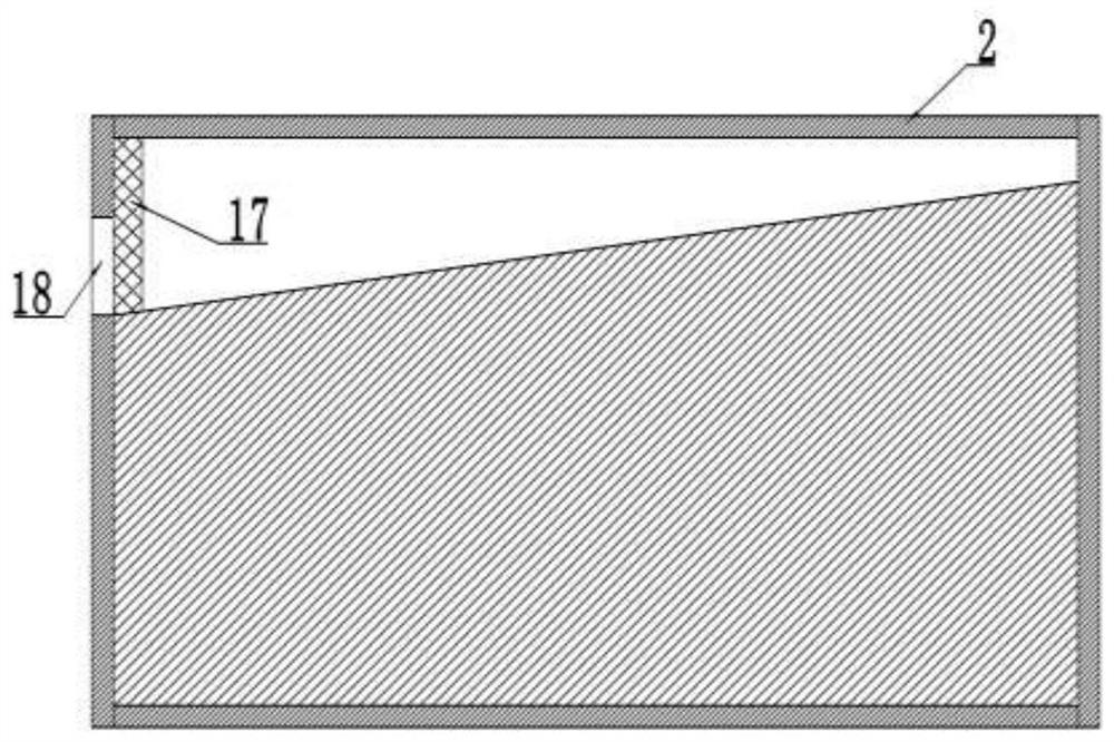
[0030] Example 2, please refer to image 3 The top of the two cover plates 2 is a slope structure, and the side walls of the cover plates 2 are provided with a water outlet 18 at the bottom of the slope, and a filter screen 17 is installed at the position of the water outlet 18, and drainage is provided on the two side walls of the box body 1 The port 20 and the drain port 20 are located above the horizontal plate 3, and the opposite ends of the two cover plates 2 are wrapped with waterproof sealing sleeves.

[0031] Working principle: when it is raining, when the rainwater falls on the cover plate 2, it will flow to the water outlet 18 along the slope, and the filter screen 17 will filter out impurities such as leaves on the cover plate 2 to prevent the water outlet 18 from being blocked. The water flow falls on the horizontal plate 3 in the left and right chambers, and then is discharged out of the box body 1 through the drain port 20 on the side wall of the box body 1, effe...

Embodiment 3

[0032] Embodiment 3, a solar cell panel 19 is installed on the top of the mobile signal lamp 6 , and the solar cell panel 19 is electrically connected to the mobile signal lamp 6 .

[0033]Working principle: when the mobile signal lamp 6 is used on a sunny day, the solar panel 19 on the top of the mobile signal lamp 6 can be charged with solar energy, and the light energy irradiated on the solar panel 19 can be converted into electrical energy for the normal use of the mobile signal lamp 6. It effectively saves resource input, and at the same time utilizes clean energy to effectively protect the ecological environment of the earth.


PUM


Abstract

The invention discloses a signal lamp with a positioning function and relates to the technical field of signal lamps. The signal lamp comprises a box body, two vertical plates are fixedly installed inthe box body, a box opening is formed in the middle of the top of the box body, two cover plates are connected to the box opening in a sliding mode, transverse plates are fixedly installed in a leftcavity and a right cavity of the box body, and telescopic mechanisms for controlling the cover plates are arranged in the left cavity and the right cavity and located above the transverse plates. A forward and reverse rotation motor is fixedly mounted in the left side cavity; an output shaft of the forward and reverse rotation motor is coaxially connected with a rotating rod, the rotating rod arranged in the middle cavity is provided with two sections of threads opposite in direction, the two sections of threads are connected with nuts, connecting rods are hinged to the nuts, a sliding plate is arranged in the middle cavity, and the top of the sliding plate is detachably connected with a movable signal lamp. According to the invention, a problem of road traffic paralysis caused by a largeamount of time for temporarily allocating and transporting traffic lights when the traffic lights fail in the prior art is solved, the operation is simple and convenient, and the practicability is high.

Description

technical field [0001] The invention relates to the technical field of signal lamps, in particular to a signal lamp with a positioning function. Background technique [0002] With the rapid development of social economy and the continuous improvement of people's living standards, motor vehicles are increasing rapidly, which directly leads to heavy traffic on urban roads, especially during peak traffic periods, when roads with large traffic volumes are extremely dependent on the command of traffic lights , especially on roads with many intersections, if there is a problem with the traffic lights at one node, it will cause traffic congestion in the entire area. [0003] Under normal circumstances, if a traffic signal light at a certain intersection fails, the traffic management department will usually quickly arrange traffic police to direct the traffic on the spot or dispatch temporary signal lights in an emergency. During this period, road traffic will be paralyzed, which w...

Claims


Application Information

Patent Timeline
IPC IPC(8): G08G1/0955
CPCG08G1/0955
Inventor 索焕志
Owner 安徽信联建设工程有限公司
Learn More