A traffic flow detection and control method

A traffic flow, detection and control technology, applied in the traffic control system, the traffic control system of road vehicles, and the control of traffic signals, etc., can solve the problems of intersection paralysis, unresponsive navigation, endangering the personal safety of drivers, etc., and improve the traffic efficiency. , avoid frequent start and stop, avoid the effect of safety hazards

Active Publication Date: 2020-11-27
山东迅鸣物联网科技有限公司
View PDF10 Cites 0 Cited by
  • Summary
  • Abstract
  • Description
  • Claims
  • Application Information

AI Technical Summary

Problems solved by technology

[0005] 2. When traffic is congested in the north-south direction of the road, the rear intersection signal light still prompts vehicles to pass, and the vehicles continue to drive into the intersection according to the green light, resulting in congestion at the intersection, making it impossible for vehicles in the east-west direction to pass, and the intersection is completely paralyzed;
[0006] 3. When the vehicle is driving in a straight line, it waits for a red light at intersection A and encounters a red light when driving to the next intersection B, and then encounters a red light at intersection C. The vehicle cannot continue to drive, and the road traffic efficiency is low;
[0007] 4. There is a lot of traffic on the road. When there is a vehicle that needs to merge from the road fork, if the straight vehicle on the road does not give way, the merging vehicle can only be forcibly inserted, otherwise it may enter an infinite wait, and the merging vehicle will easily lead to Traffic jams, and even cause traffic accidents, endangering the personal safety of drivers;
[0009] Sixth, the current GPS system cannot provide centimeter-level positioning accuracy when important vehicles are passing on the road, and it is easy to cause slow navigation response and high-precision lane navigation at forks

Method used


Image

  • A traffic flow detection and control method
  • A traffic flow detection and control method
  • A traffic flow detection and control method

Examples


Embodiment Construction

[0039] The following will clearly and completely describe the technical solutions in the embodiments of the present invention with reference to the accompanying drawings in the embodiments of the present invention. Obviously, the described embodiments are only some, not all, embodiments of the present invention.

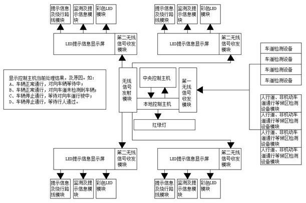
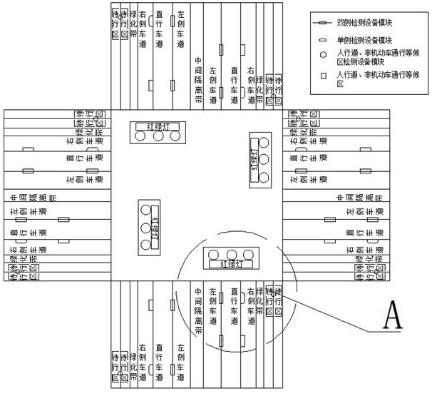
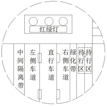
[0040] refer to Figure 1-12 , a traffic flow detection and control method, including a traffic flow detection and control system and a centimeter-level positioning scheme, the traffic flow detection and control system includes a regional control server for regional traffic flow management; a local control host for current intersection traffic flow management, summarized The detected road traffic information, and calculate the optimal result according to the dispatching information of the regional control server and the traffic information and control plan of neighbor intersections, and control it; the lane detection equipment module used to detect vehicles in the mot...


PUM


Abstract

The invention discloses a traffic flow detection control method, and the method comprises a traffic flow detection control system and a centimeter-level setting scheme. The traffic flow detection control system comprises a central control unit which is used for the regional traffic flow management; a local control unit which is used for the traffic flow management of a current road intersection; alane detection equipment module which is used for detecting a vehicle in a motor vehicle lane; a first wireless signal receiving and transmitting module which is used for receiving the data of the detection equipment module; and a wireless signal transmitting module which is used for transmitting a main unit control instruction. The method can achieve the coordinative control of the signal lampsand an LED prompt information display screen at each road intersection according to the traffic flow conditions of all roads, facilitates the control and guide, enables the vehicles to continuously move, avoids the frequent start / stop of the vehicles, improves the traffic efficiency of the roads, avoids the congestion of the roads, and avoids the potential safety hazards caused by the road scramble.

Description

technical field [0001] The invention relates to the technical field of traffic flow control, in particular to a traffic flow detection and control method. Background technique [0002] Traffic flow refers to the number of traffic entities passing through a certain location, a certain section or a certain lane of the road within a selected time period. From the size of the traffic flow, the traffic congestion can be judged, so as to decide what traffic management measures to take. Therefore, Accurate detection of traffic volume occupies a very important position in traffic engineering. [0003] The current road traffic signal lights are controlled by the fixed setting time to complete the traffic light control, which cannot be automatically adjusted according to the actual road conditions. It is easy to cause traffic congestion scenarios such as the following: [0004] 1. The traffic flow in the north-south direction is congested, and there is no traffic in the east-west di...

Claims


Application Information

Patent Timeline
Patent Type & Authority Patents(China)
IPC IPC(8): G08G1/08G08G1/09G08G1/0967G08G1/07
CPCG08G1/07G08G1/08G08G1/09G08G1/0967
Inventor 于建洋
Owner 山东迅鸣物联网科技有限公司
Why Eureka
Try Eureka