
Waste gas suction and purification device and using method thereof

A purification device and exhaust gas technology, applied in chemical instruments and methods, separation methods, transportation and packaging, etc., can solve the problems of not being able to process them into valuable products, not being able to actively control the emission direction, and being built at the downwind outlet, so as to avoid disadvantages Influence, reduce the difficulty of adjustment, improve the effect of adaptability

Inactive Publication Date: 2020-11-10
苏州雷沃克环保科技有限公司
View PDF12 Cites 0 Cited by
  • Summary
  • Abstract
  • Description
  • Claims
  • Application Information

AI Technical Summary

Problems solved by technology

[0004] However, even if the exhaust gas is specified at the source, the exhaust gas will always have a certain impact on the environment, and the existing exhaust gas purification device does not have the function of recovering the waste gas filtration residue and then processing it into valuable products. Solve the problem of exhaust gas emission from the perspective of economic interests, and most of the exhaust gas emission devices are built at the downwind outlet, which cannot actively control the direction of emission, and is subject to geographical restrictions

Method used


Image

  • Waste gas suction and purification device and using method thereof
  • Waste gas suction and purification device and using method thereof
  • Waste gas suction and purification device and using method thereof

Examples


Embodiment Construction

[0039] The following will clearly and completely describe the technical solutions in the embodiments of the present invention with reference to the accompanying drawings in the embodiments of the present invention. Obviously, the described embodiments are only some, not all, embodiments of the present invention. Based on the embodiments of the present invention, all other embodiments obtained by persons of ordinary skill in the art without making creative efforts belong to the protection scope of the present invention.

[0040] In the description of the present invention, references to "an embodiment," "one embodiment," "some embodiments," or "other embodiments" mean that a particular feature, structure, or characteristic described in connection with the embodiments is included in at least some of the embodiments. in, but not necessarily all of the examples. Multiple occurrences of "an embodiment," "one embodiment," or "some embodiments" are not necessarily all referring to th...


PUM


Abstract

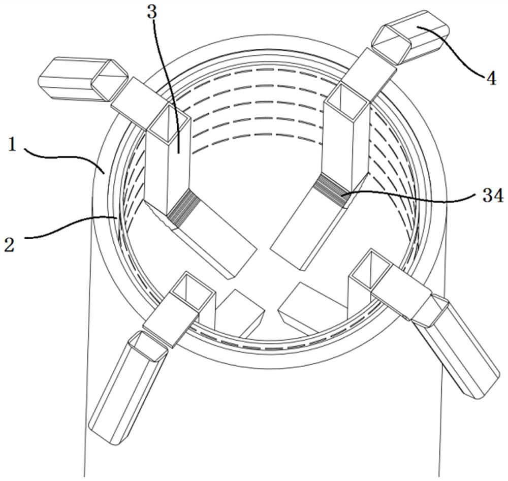
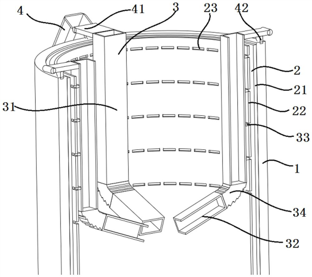
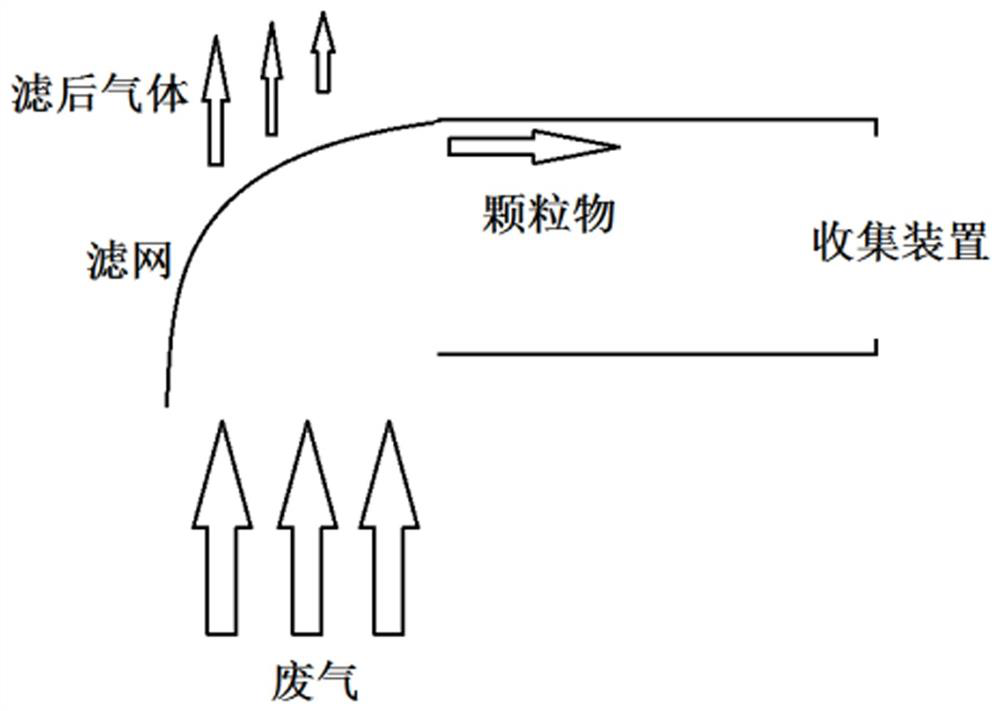
The invention discloses a waste gas suction and purification device and a using method thereof. The device comprises an exhaust pipeline and a filter mechanism connected to the exhaust pipeline. The filter mechanism comprises a plurality of filter pipes and gas ejector pipes in one-to-one correspondence with the filter pipes; the filter pipes are movably connected with the corresponding air injection pipes; the filter pipes are parallel to the axial direction of the exhaust pipeline; each filter pipe is an axially-through hollow pipe body, a filter screen is arranged in each filter pipe, and acollecting device is arranged near each filter screen. A flexible material section is arranged on each filter pipe and divides each filter pipe into a first filter pipe and a second filter pipe. Eachfirst filter pipe is connected to the side, close to an upper opening of the exhaust pipeline, of the corresponding flexible material section; each second filter pipe is connected to the side, away from the upper opening of the exhaust pipeline, of the corresponding flexible material section. A rotating mechanism is arranged in each filter pipe. By changing the suction position in the exhaust pipeline, the exhaust gas suction efficiency can be adjusted in time, and filtered residual exhaust gas can be blown away from the control area.

Description

technical field [0001] The invention relates to a waste gas treatment device, in particular to a waste gas suction and purification device and a use method thereof. Background technique [0002] Exhaust gas refers to the poisonous and harmful gas emitted by human beings in the process of production and life. Especially chemical plants, steel plants, pharmaceutical plants, coking plants, oil refineries, etc., and the production of domestic waste gas from human life, the exhaust gas has a strong smell, which seriously pollutes the environment and affects human health. Industrial waste gas emitted by various production enterprises is an important source of air pollutants. If a large amount of industrial waste gas is discharged into the atmosphere without treatment and reaches the standard, it will inevitably reduce the quality of the atmospheric environment, bring serious harm to human health, and cause huge losses to the national economy. Toxic and harmful substances in indu...

Claims


Application Information

Patent Timeline
IPC IPC(8): B01D46/00B01D46/12B01D46/48
CPCB01D46/0041B01D46/12B01D46/48B01D46/56
Inventor 张美林冯强
Owner 苏州雷沃克环保科技有限公司
Learn More