A joint structure of a ceramic plate and a metal cylindrical member

A joint structure, metal technology, used in metal processing, metal processing equipment, welding equipment, etc., can solve the problems of joint peeling, ceramic plate cracks, etc., and achieve the effect of convenient welding, strengthening welding strength, and excellent tempering.

Active Publication Date: 2021-08-17
ANHUI POLYTECHNIC UNIV
View PDF6 Cites 0 Cited by
  • Summary
  • Abstract
  • Description
  • Claims
  • Application Information

AI Technical Summary

Problems solved by technology

[0003] For this reason, how to combine the metal gas inlet tube with the ceramic plate has become an extremely important technical key, and as the joining method of the ceramic plate and the metal gas inlet tube, in the prior art, the ceramic plate and the gas Solder is filled between the inlet pipes for welding, but during brazing, since the gas inlet pipe and the solder shrink more than the ceramic plate when it cools, the stress caused by the difference in thermal expansion during welding will cause cracks in the ceramic plate , even if the ceramic plate is prevented from cracking during welding, and after welding, repeated use of the electrostatic chuck for thermal cycle, for the same reason, the joint will be peeled off, and even the ceramic plate will be cracked again

Method used


Image

  • A joint structure of a ceramic plate and a metal cylindrical member
  • A joint structure of a ceramic plate and a metal cylindrical member
  • A joint structure of a ceramic plate and a metal cylindrical member

Examples


Embodiment Construction

[0024] The following will clearly and completely describe the technical solutions in the embodiments of the present invention with reference to the accompanying drawings in the embodiments of the present invention. Obviously, the described embodiments are only some, not all, embodiments of the present invention. Based on the embodiments of the present invention, all other embodiments obtained by persons of ordinary skill in the art without making creative efforts belong to the protection scope of the present invention.

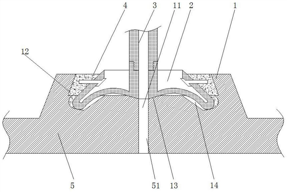
[0025] see Figure 1-6 , an embodiment provided by the present invention: a joint structure between a ceramic plate and a metal cylindrical part, including a ceramic plate 5 having a through hole 51 and a metal cylinder 3, and the ceramic plate 5 above the through hole 51 The top is provided with a protruding part 1, and the middle position of the protruding part 1 is sequentially provided with a connecting groove 12, a tapered positioning groove 13 and a thro...


PUM


Abstract

The invention discloses a joint structure between a ceramic plate and a metal cylindrical part, which comprises a ceramic plate with a through hole 1 and a metal cylinder, a protrusion is provided on the top of the ceramic plate above the through hole 1, and the The middle position of the protruding part is provided with connecting grooves, tapered positioning grooves and through hole 2 sequentially from top to bottom. The bottom end of the manufacturing cylinder is threaded with a welding seat, which is arranged in the middle of the joint groove, and the welding seat includes a cylindrical part, an annular positioning part, a fan-shaped transition part, a fan-shaped material retaining part, and a ceramic nail. The invention "transfers" the solder soldered in the prior art to the side, so that when the electrostatic chuck is used for thermal cycling, the temperature of the solder seat, solder, and the junction of the ceramic board is reduced from high to low, thereby reducing the size of the ceramic board. And the amount of expansion and contraction of the solder prevents the peeling of the soldered part and further improves the soldering strength.

Description

technical field [0001] The invention relates to the technical field of joint structures, in particular to a joint structure between a ceramic plate and a metal cylindrical part. Background technique [0002] An electrostatic chuck is used as a holding member for sucking a wafer and controlling the temperature of the wafer in a semiconductor manufacturing process. As such an electrostatic chuck, it is known that metal is bonded from the back side of a disc-shaped ceramic plate provided with gas introduction holes. An electrostatic chuck that improves thermal conductivity by making a gas introduction tube to supply He gas, etc., to the adsorption surface of the wafer. [0003] For this reason, how to combine the metal gas inlet tube with the ceramic plate has become an extremely important technical key, and as the joining method of the ceramic plate and the metal gas inlet tube, in the prior art, the ceramic plate and the gas Solder is filled between the inlet pipes for weldi...

Claims


Application Information

Patent Timeline
Patent Type & Authority Patents(China)
IPC IPC(8): B23K3/08B23K3/00B23K103/00B23K103/18
CPCB23K3/00B23K3/085B23K2103/18B23K2103/52
Inventor 王刚刘一贺杨云龙王秒赵禹
Owner ANHUI POLYTECHNIC UNIV
Why Eureka
Try Eureka