


Quick Research
Generate reliable direction feasibility study reports for your R&D in just a few steps.

Technical Q&A
Discover and master advanced knowledge NOW. Basics, ideas, possibilities, all at once.

Find Solutions
As an expert in R&D theories, this can generate solutions to your technical problems instantly.

Evaluate Feasibility
Analyze your overall solution with one click, know your potential R&D risks in advance.

Monitor Landscape
Get weekly tech updates, stay abreast of the latest tech innovations and key insights.
Thermoacoustic device
A thermoacoustic and diaphragm technology, which is used in hot gas variable capacity engine devices, heat pumps, lighting and heating equipment, etc., can solve problems such as changes in working gas filling pressure, and achieve the effect of improving work efficiency.
- Summary
- Abstract
- Description
- Claims
- Application Information
AI Technical Summary
Problems solved by technology
Method used
Image


Examples
Embodiment Construction
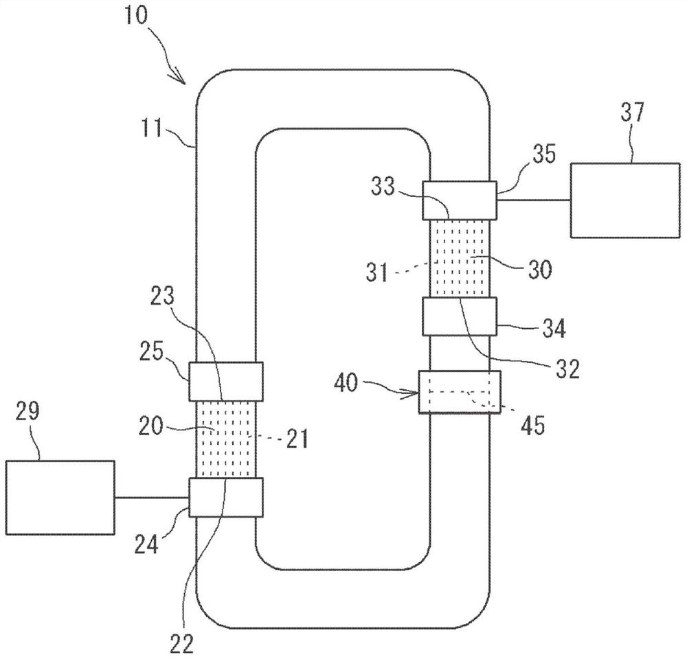
[0019] figure 1 is a configuration diagram schematically showing an example of the thermoacoustic device 10 . The thermoacoustic device 10 of the present disclosure includes a collar 11 , and a first stack 20 and a second stack 30 each disposed in the collar 11 . The working gas is sealed in the collar 11 . The working gas is, for example, air, nitrogen, helium, argon or a mixture of at least two of them.
[0020] The first stack 20 is a columnar member, and has a plurality of micro flow paths 21 extending through the collar 11 in the axial direction of the collar 11 . The second stack 30 is also a columnar member, and has a plurality of micro flow paths 31 extending through the collar 11 in the axial direction of the collar 11 . The micro flow paths 21, 31 serve as passages for the working gas.
[0021] In the axial direction, a temperature gradient occurs between the first end 22 and the second end 23 of the first stack 20 . In the present disclosure, the temperature at...
PUM
 Abstract
Description
Claims
Application Information
 - R&D Engineer
- R&D Manager
- IP Professional
- Industry Leading Data Capabilities
- Powerful AI technology
- Patent DNA Extraction
Browse by: Latest US Patents, China's latest patents, Technical Efficacy Thesaurus, Application Domain, Technology Topic, Popular Technical Reports.
© 2024 PatSnap. All rights reserved.Legal|Privacy policy|Modern Slavery Act Transparency Statement|Sitemap|About US| Contact US: help@patsnap.com