
Intelligent electric control valve

An electronically controlled valve, intelligent technology, applied in the direction of valve details, valve devices, valve operation/release devices, etc., can solve the problems of increasing the time for personnel to maintain equipment, increasing the pipeline installation cycle, and reducing the actual reliability of pipelines, etc.

Inactive Publication Date: 2020-11-10
杨桂英
View PDF6 Cites 0 Cited by
  • Summary
  • Abstract
  • Description
  • Claims
  • Application Information

AI Technical Summary

Problems solved by technology

[0002] Common electronic control valves use electromagnetic or motor to drive the corresponding blocking block to move to separately connect and disconnect the pipelines, which results in the fact that there will be many pipelines in the actual use of the equipment However, there is no way to use a single electronically controlled valve to control various pipelines. More pipelines and more valves need to be set up to achieve interlaced control between various pipeline liquids. The disadvantages of the above design On the one hand, it increases the time for personnel to maintain the equipment, and the cost of the specific setting of the above equipment is high, and it cannot be installed and used in large quantities in a short time, which causes the installation period of the corresponding pipeline to increase. Due to the above installation period The increase will also reduce the actual reliability of the corresponding pipelines for maintenance. Due to the above shortcomings, the stability of the equipment in actual use will be reduced, and it will greatly consume the energy and time of personnel.

Method used


Image

  • Intelligent electric control valve
  • Intelligent electric control valve
  • Intelligent electric control valve

Examples


Embodiment Construction

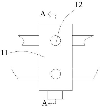
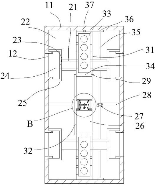
[0023] Such as Figure 1-Figure 7 As shown, the present invention is described in detail. For the convenience of description, the orientations mentioned below are now stipulated as follows: figure 1 The up, down, left, right, front and back directions of the projection relationship itself are consistent. An intelligent electronically controlled valve of the present invention includes an installation box 11. Several connecting pipes 12 are arranged in the installation box 11. The installation box 11 is provided with Inner chamber 22, said inner chamber 22 is provided with a number of outer housings 25, said outer housing 25 is provided with a chamber 24, said chamber 24 communicates with said connecting pipe 12, said outer housing 25 is provided with a perforation 23, the perforation 23 communicates with the cavity 24, a matching pipe 21 is provided on one side of the outer casing 25, and a lifting slide 29 is provided on one side of the matching pipe 21. The sliding cylinder ...


PUM


Abstract

The invention discloses an intelligent electric control valve which comprises an installing box body. A plurality of connecting pipelines are arranged in the installing box body in a communicating manner. An inner cavity is formed in the installing box body. A plurality of outer shells are arranged in the inner cavity. A containing cavity is formed in each outer shell. The containing cavities andthe connecting pipelines are arranged in a communicating manner. Penetration holes are formed in the outer shells and communicate with the containing cavities. A matched pipeline is arranged on one side of each outer shell. A lifting sliding cylinder is arranged on one side of each matched pipeline. A penetration hole is formed in each lifting sliding cylinder. A plurality of connecting holes areformed in each penetration hole in a communicating manner. The equipment adopts and is provided with the plurality of connecting pipelines. Water can be introduced from any connecting pipeline, then the water flows in the plurality of connecting pipelines, and the purpose of such design is to enable the connecting pipelines to communicate with multiple pipelines at the same time so as to solve theproblem of arrangement cost of the valve and the pipelines.

Description

technical field [0001] The invention relates to the technical field of electric control valve equipment, in particular to an intelligent electric control valve. Background technique [0002] Common electronic control valves use electromagnetic or motor to drive the corresponding blocking block to move to separately connect and disconnect the pipelines, which results in the fact that there will be many pipelines in the actual use of the equipment However, there is no way to use a single electronically controlled valve to control various pipelines. More pipelines and more valves need to be set up to achieve interlaced control between various pipeline liquids. The disadvantages of the above design On the one hand, it increases the time for personnel to maintain the equipment, and the cost of the specific setting of the above equipment is high, and it cannot be installed and used in large quantities in a short time, which causes the installation period of the corresponding pipel...

Claims


Application Information

Patent Timeline
Patent Type & Authority Applications(China)
IPC IPC(8): F16K31/04F16K31/53
CPCF16K31/04F16K31/53
Inventor 杨桂英
Owner 杨桂英
Features
  • Generate Ideas
  • Intellectual Property
  • Life Sciences
  • Materials
  • Tech Scout
  • Unparalleled Data Quality
  • Higher Quality Content
  • 60% Fewer Hallucinations
Learn More