
a plate moving machine

A mobile machine and mobile mechanism technology, applied in the field of mobile machines, can solve problems such as easy frostbite, high difficulty coefficient of work, easy soreness and swelling of hands, and achieve the effects of preventing back and forth sliding, enhancing the scope of application, and saving manpower consumption

Active Publication Date: 2022-07-05
嘉兴市名人电器股份有限公司
View PDF0 Cites 0 Cited by
  • Summary
  • Abstract
  • Description
  • Claims
  • Application Information

AI Technical Summary

Problems solved by technology

[0002] With the rapid development of society, some milk tea shops have introduced a new way of eating milk tea. Workers hold a cup containing milk tea in one hand and pour the milk tea from the top of the ice machine, and move the plate back and forth at the bottom of the ice machine with the other hand. Evenly put the crushed milk tea ice into the plate. This operation not only requires the cooperation of both hands, but also makes the work more difficult. Moreover, the hand holding the plate is prone to frostbite due to long-term contact with the crushed ice. In addition, holding the plate body for a long time Moving back and forth, the hands are prone to soreness and swelling, which increases the risk of the plate body falling off the hand

Method used


Image

  • a plate moving machine
  • a plate moving machine
  • a plate moving machine

Examples


Embodiment 1

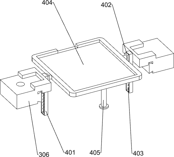
[0053] A plate mover such as figure 1 As shown, it includes a bottom plate 1, a mounting plate 2, a moving mechanism 3 and a placing mechanism 4. The top of the bottom plate 1 is provided with mounting plates 2 on the left and right sides, and the top of the mounting plate 2 is provided with a moving mechanism 3. The right part of the moving mechanism 3 and The top of the base plate 1 is connected, and a placing mechanism 4 is arranged between the moving mechanisms 3 on the left and right sides.

[0054] When it is necessary to use the machine to drive the plate body 7 to catch the milk tea crushed ice, first place the plate body 7 on the placing mechanism 4, then start the moving mechanism 3, the moving mechanism 3 drives the placing mechanism 4 to move back and forth, and the placing mechanism 4 drives the plate body 7 Move back and forth to make the plate body 7 evenly catch the milk tea crushed ice, then close the moving mechanism 3, remove the plate body 7 with the milk t...

Embodiment 2

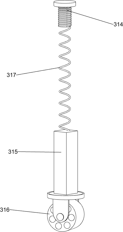
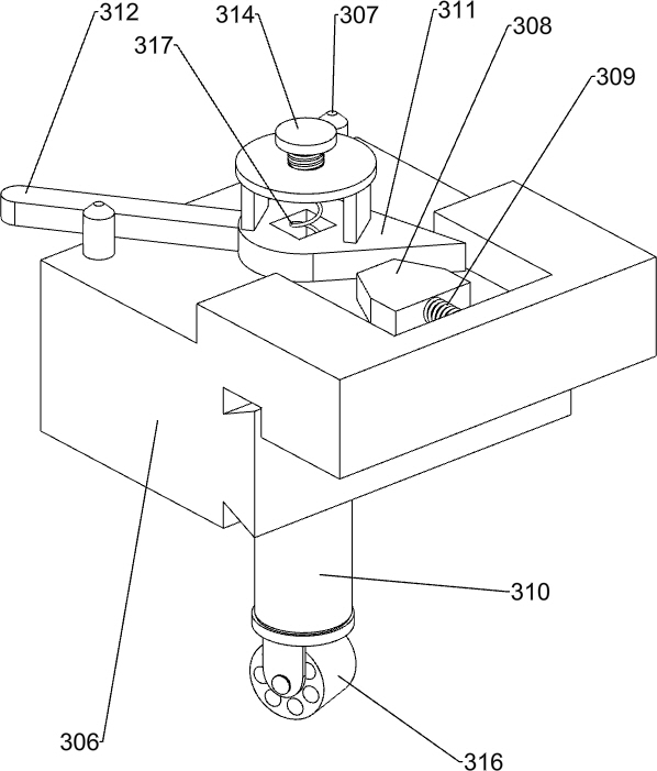
[0056] On the basis of Example 1, as Figure 2-6As shown, the moving mechanism 3 includes a special-shaped plate 301, a rotating rod 302, a roller 303, a motor 304, a first sliding rail 305, a first sliding block 306, a limit rod 307, a clamping plate 308, a first spring 309, a cylinder 310 , turning plate 311, swing plate 312, disc 313, first bolt 314, square rod 315, wheel 316 and second spring 317, special-shaped plates 301 are provided on the front and rear sides on the right side of the top of the bottom plate 1, and the middle of the special-shaped plate 301 is rotated. There is a rotating rod 302, a roller 303 is sleeved on the rotating rod 302, and the roller 303 is located between the special-shaped plates 301 on the front and rear sides. Connection, the tops of the mounting plates 2 on the left and right sides are provided with first slide rails 305, the first slide rails 305 are slidably provided with first sliders 306, and the top of the first slide block 306 on th...

Embodiment 3

[0061] On the basis of Example 2, as Figure 7-9 As shown, it also includes a toggle mechanism 5. The toggle mechanism 5 includes a third slide rail 501, a third slider 502, a second bolt 504, a vertical rod 505 and a toggle rod 506. The top right side of the bottom plate 1 is provided with a third Three slide rails 501, the third slide rail 501 is located on the right side of the special-shaped plate 301, the third slide rail 501 is slidably provided with a third slide block 502 at the front and rear, and an opening 503 is opened on the right side of the third slide rail 501, and the third slide rail 501 The right side of the block 502 is connected with second bolts 504 by means of bolts, and the second bolts 504 pass through the opening 503 .

[0062] Adjust the toggle mechanism 5 according to the size of the plate, first loosen the second bolt 504, then move the third slider 502 back and forth, after finding a suitable position, tighten the second bolt 504, when the wheel 3...


PUM


Abstract

The present invention relates to a moving machine, in particular to a plate moving machine. The purpose of the present invention is to provide a plate moving machine that can automatically drive the plate body to move back and forth, and is suitable for plate bodies of different sizes. The invention provides such a plate moving machine, which is characterized by comprising: a bottom plate, a mounting plate is arranged on the top of the bottom plate; a moving mechanism, a moving mechanism is arranged on the top of the mounting plate, and the bottom of one side of the moving mechanism is connected with the top of the bottom plate; a placing mechanism, A placing mechanism is arranged between the moving mechanisms on the left and right sides. Using the moving mechanism, the placing mechanism can be driven to move back and forth, saving manpower consumption; through the placing mechanism, plates of different sizes can be placed on the placing frame, which enhances the application range of the plate; the toggle mechanism can replace the manual swinging of the pendulum by workers. The plate can realize the cyclic movement of the placing frame back and forth, and the clamping mechanism can fix the plate bodies of different sizes on the top of the placing frame.

Description

technical field [0001] The present invention relates to a moving machine, in particular to a plate moving machine. Background technique [0002] With the rapid development of society, some milk tea shops have introduced a new way of eating milk tea. The worker holds a cup with milk tea in one hand, pours the milk tea from the top of the ice-making machine, and moves the plate back and forth at the bottom of the ice-making machine with the other hand. The milk tea crushed ice is evenly placed into the plate. This operation not only requires the cooperation of both hands, and the work is difficult, but also the hands holding the plate are easily frostbitten due to long-term contact with the crushed ice. In addition, the plate body is held for a long time. Moving back and forth can make your hands sore and swollen, increasing the risk of the plate body falling off your hands. [0003] In order to improve the problems in the above manufacturing method, it is necessary to design...

Claims


Application Information

Patent Timeline
Patent Type & Authority Patents(China)
IPC IPC(8): F25C5/12
CPCF25C5/12Y02E60/10
Inventor 不公告发明人
Owner 嘉兴市名人电器股份有限公司
Learn More