A laser-mechanical rock breaking test device

A test device and laser technology, which is applied in the new field of high-efficiency rock breaking and laser-mechanical rock breaking in oil and gas drilling, can solve the problems of not being widely used, low drilling efficiency, narrow application range, etc., and achieve the safety of optical path and gas path system Reliable, functional, high-precision results

Active Publication Date: 2022-07-22
SOUTHWEST PETROLEUM UNIV
View PDF10 Cites 0 Cited by
  • Summary
  • Abstract
  • Description
  • Claims
  • Application Information

AI Technical Summary

Problems solved by technology

[0003] At present, in response to the low drilling efficiency in deep, ultra-deep and complex formations that are difficult to drill, many new rock-breaking technologies have been proposed at home and abroad, such as shock-absorbing rock-breaking, thermal jet rock-breaking, ultrasonic rock-breaking and other technologies, but These technologies cannot be widely used due to problems such as narrow scope of application and low efficiency. Laser-mechanical rock breaking is a brand-new drilling concept. , greatly reducing rock strength and improving rock drillability, thereby providing favorable conditions for subsequent mechanical rotary drilling. Laser-mechanical rock breaking technology can greatly improve the efficiency of mechanical rock breaking, with a wide range of applications and high efficiency
[0004] Emphasizing the research on the basic scientific theory of laser-mechanical rock breaking is of great significance to the development of my country's drilling engineering discipline. Today's laser-mechanical rock breaking technology is still in the experimental research stage. A fully functional and well-designed test device is important for The role of the research on this technology is undoubtedly very huge, so in order to conduct in-depth theoretical and experimental research on this technology, the present invention designs a laser-mechanical rock breaking test device

Method used


Image

  • A laser-mechanical rock breaking test device
  • A laser-mechanical rock breaking test device
  • A laser-mechanical rock breaking test device

Examples


Embodiment Construction

[0021] The structure of the present invention will be further described below with reference to the accompanying drawings and this embodiment.

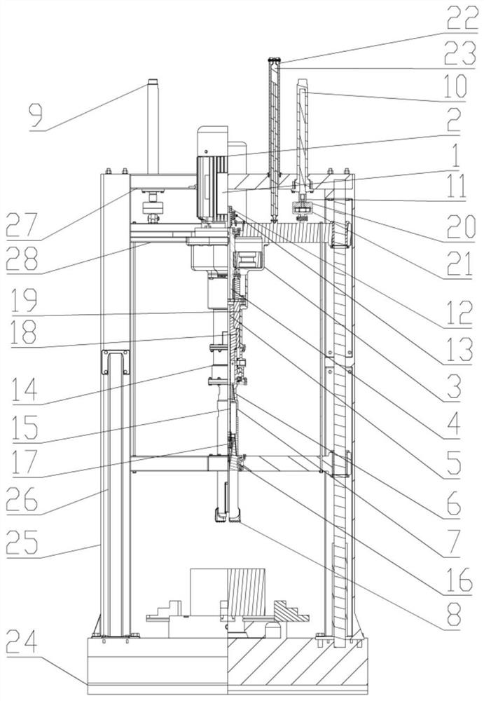
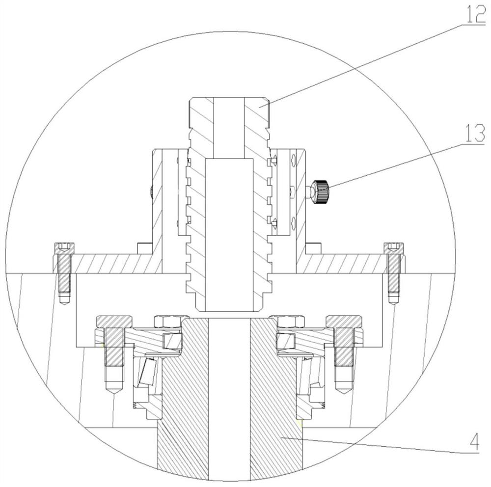
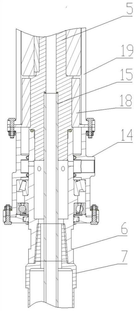
[0022] like figure 1 As shown in the figure, a laser-mechanical rock breaking test device is mainly composed of a rotating system, a hydraulic control system, an optical circuit and a gas circuit system, a testing and data processing system, and a supporting system: the rotating system is mainly composed of a frequency converter 1, a motor 2, a reducer 3. The output shaft of the reducer 4, the dynamic torque sensor shaft 5, the drill pipe joint 6, the drill pipe 7, and the drill bit 8 are composed of, among which, the motor 2 can realize stepless speed regulation through the frequency converter 1, and the motor 2 is connected vertically by bolts. At the upper end of the main beam 28 , the output shaft of the motor 2 is connected to the reducer 3 , the box of the reducer 3 is fixed to the lower end of the main beam 28 by bolting, and t...


PUM


Abstract

A laser-mechanical rock breaking test device is mainly composed of a rotation system, a hydraulic control system, an optical path and a gas path system, a test and data processing system, and a support system; the rotation system is mainly composed of a motor, a reducer, a drill pipe, and a drill bit. The hydraulic control system is mainly composed of a hydraulic cylinder and a telescopic rod. The optical path and the gas path system are mainly composed of a laser head, a laser head angle adjuster, an air inlet disc, and a phosgene mixing cylinder. The laser head angle adjuster can adjust the emission angle of the laser. Adjustment, the laser and gas are mixed in the phosgene mixing cylinder, and finally act on the bottom of the drill bit. The test and data processing system is mainly composed of a torque sensor, a spoke pressure sensor, and a displacement sensor. The support system is mainly composed of a base and a main column. The laser-mechanical rock-breaking test device of the present invention can carry out research on the laser-mechanical rock-breaking mechanism, efficient synergistic parameter matching, etc., and is of great significance for promoting the development of the laser-mechanical rock-breaking technology.

Description

technical field [0001] The invention relates to the technical field of high-efficiency rock-breaking in oil and gas drilling, in particular to the new technology field of laser-mechanical rock-breaking. Background technique [0002] The key to increasing the speed of oil and gas development is to increase the drilling speed, and the key to increasing the drilling speed is the efficient rock-breaking technology and equipment. At present, the main battlefield of my country's oil and gas exploration and development has gradually shifted to deep, ultra-deep, complex and difficult-to-drill strata and unconventional strata, and the difficulty of drilling has increased sharply. , low rock breaking efficiency, slow drilling speed and high cost have become one of the main bottlenecks restricting the efficient exploration and development of my country's oil and gas resources. Therefore, there is an urgent need for new high-efficiency rock-breaking drilling technologies and equipment t...

Claims


Application Information

Patent Timeline
Patent Type & Authority Patents(China)
IPC IPC(8): G01N33/24
CPCG01N33/24
Inventor 张文琳黄志强黄泽川何林陈科邓嵘马亚超傅世奇翟预立梁耀文
Owner SOUTHWEST PETROLEUM UNIV
Why Eureka
Try Eureka