Check patentability & draft patents in minutes with Patsnap Eureka AI!

Light source device

A technology of light source device and light-transmitting parts, which is applied in the direction of lasers, laser parts, semiconductor lasers, etc., and can solve problems such as difficulty in conformity

Active Publication Date: 2020-11-10
LITE ON OPTO TECH (CHANGZHOU) CO LTD +1
View PDF10 Cites 0 Cited by
  • Summary
  • Abstract
  • Description
  • Claims
  • Application Information

AI Technical Summary

Problems solved by technology

[0002] Most of the existing light source devices are packaged in TO-CAN (Transistor Outline-CAN Transistor Outline Can), and there has not been a major structural improvement in recent years, so it is gradually difficult to meet various requirements

Method used


Image

  • Light source device
  • Light source device
  • Light source device

Examples


Embodiment Construction

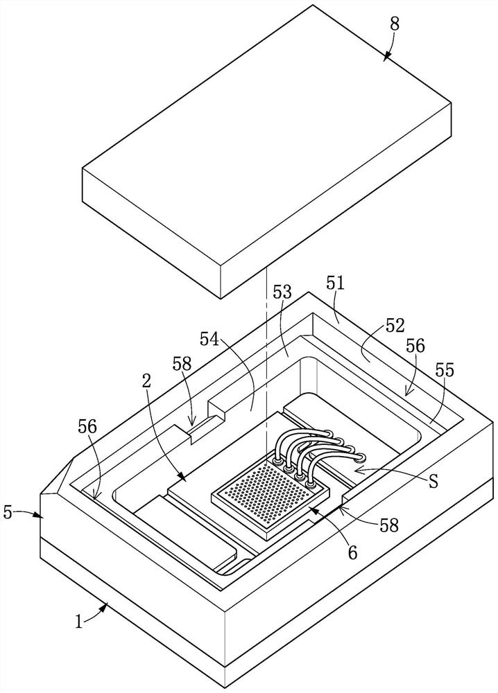
[0024] see Figure 1 to Figure 16 , which is an embodiment of the present invention. What needs to be explained first is that this embodiment corresponds to the relevant quantities and shapes mentioned in the drawings, and is only used to specifically illustrate the implementation of the present invention, so as to facilitate the understanding of the content of the present invention. , not to limit the protection scope of the present invention.

[0025] This embodiment discloses a light source device 100, especially a light source device 100 for three-dimensional sensing, such as a light source device 100 using a vertical-cavity surface-emitting laser (Vertical-Cavity Surface-Emitting Laser, VCSEL) or an infrared lamp. The present invention is not limited thereto, and the light source device 100 may also be a light emitting diode (LED) or a laser (Laser).

[0026] Such as Figure 1 to Figure 3 As shown, it discloses a basic structure; that is, the basic structure can be adju...


PUM

PropertyMeasurementUnit
Particle sizeaaaaaaaaaa

Abstract

The invention discloses a light source device. The device comprises a substrate, an upper electrode layer and a lower electrode layer which are arranged on the two sides of the substrate respectively,a light-emitting unit which is installed on the upper electrode layer, an enclosing wall which is arranged on the substrate and surrounds the light-emitting unit, a conductive unit which is arrangedon the enclosing wall and electrically coupled to the lower electrode layer, a light-transmitting part which is arranged on the enclosing wall, a detection loop formed on the light-transmitting part,and a plurality of conductive bonding parts. The conductive unit comprises a plurality of upper connection pads far away from the substrate, and the detection loop comprises a plurality of connectionpoints adjacent to the plurality of upper connection pads. Each conductive bonding part comprises a colloid and a plurality of supporting bodies embedded in the colloid, and the colloid and the supporting bodies of each conductive bonding part are partially filled in the gap, so the plurality of contacts are electrically coupled to the plurality of upper connecting pads through the plurality of conductive bonding parts. Therefore, the supporting body of the conductive bonding part is filled into the gap between the enclosing wall and the light-transmitting piece, and the conductive bonding parts and the upper connecting pad of the enclosing wall are not collapsed due to the gap, so a better electric connection bridge is formed.

Description

technical field [0001] The invention relates to a light source device, in particular to a light source device with a conductive bonding part of a support body. Background technique [0002] Most of the existing light source devices are packaged in TO-CAN (Transistor Outline-CAN Transistor Outline Can). In recent years, there has been no significant structural improvement, so it is gradually difficult to meet various requirements. Therefore, the inventor of the present invention believes that the above-mentioned defects can be improved, so he devoted himself to research and combined with the application of scientific principles, and finally proposed an invention with reasonable design and effective improvement of the above-mentioned defects. Contents of the invention [0003] The embodiment of the present invention is to provide a light source device, which can effectively improve the possible defects of the existing light source device. [0004] The embodiment of the pres...

Claims


Application Information

Patent Timeline
IPC IPC(8): H01S5/183
CPCH01S5/183
Inventor 李文洪祥致吕大鹏杨淑桦苏渝宏
Owner LITE ON OPTO TECH (CHANGZHOU) CO LTD
Features
  • R&D
  • Intellectual Property
  • Life Sciences
  • Materials
  • Tech Scout
  • Unparalleled Data Quality
  • Higher Quality Content
  • 60% Fewer Hallucinations
Learn More