Impact-resistant combined cable bridge

A cable bridge and combined technology, which is applied in the direction of electrical components, springs/shock absorbers, vibration suppression adjustment, etc., can solve the problems of internal cable pulling, inability to separate cables, and cable aggregation, etc., to improve impact resistance and improve heat dissipation Excellent performance, easy installation and operation

Pending Publication Date: 2020-11-10
镇江市神龙电器管件有限公司
View PDF0 Cites 13 Cited by
  • Summary
  • Abstract
  • Description
  • Claims
  • Application Information

AI Technical Summary

Problems solved by technology

[0002] Cable bridges are divided into trough type, tray type, ladder frame type and grid type, etc., which are composed of brackets, brackets and installation accessories. The bridges in buildings can be erected independently or attached to various buildings and pipe gallery brackets. In terms of structure, it should reflect the characteristics of simple structure, beautiful appearance, flexible configuration and convenient maintenance. All parts need to be galvanized. If the bridge frame installed in the open air outside the building is near the sea or belongs to the corrosion area, the material must have Anti-corrosion and moisture-resistant, the combined bridge is the second-generation product of the cable bridge. It is suitable for various projects, various units and various cables. It has the characteristics of simple structure, flexible configuration, convenient installation and novel form. The combined cable tray has a single function and cannot separate the cables. The heat dissipation effect is not good, and it is easy to cause a large amount of heat to accumulate between the cables, which affects the service life of the cable. Moreover, the impact resistance is poor, and it is easy to cause internal cable pull. The bridge is easily deformed and affects the service life. Therefore, we propose an impact-resistant combined cable bridge to solve the above defects

Method used


Image

  • Impact-resistant combined cable bridge
  • Impact-resistant combined cable bridge
  • Impact-resistant combined cable bridge

Examples


Embodiment Construction

[0027] The following will clearly and completely describe the technical solutions in the embodiments of the present invention with reference to the accompanying drawings in the embodiments of the present invention. Obviously, the described embodiments are only some, not all, embodiments of the present invention. Based on the embodiments of the present invention, all other embodiments obtained by persons of ordinary skill in the art without making creative efforts belong to the protection scope of the present invention.

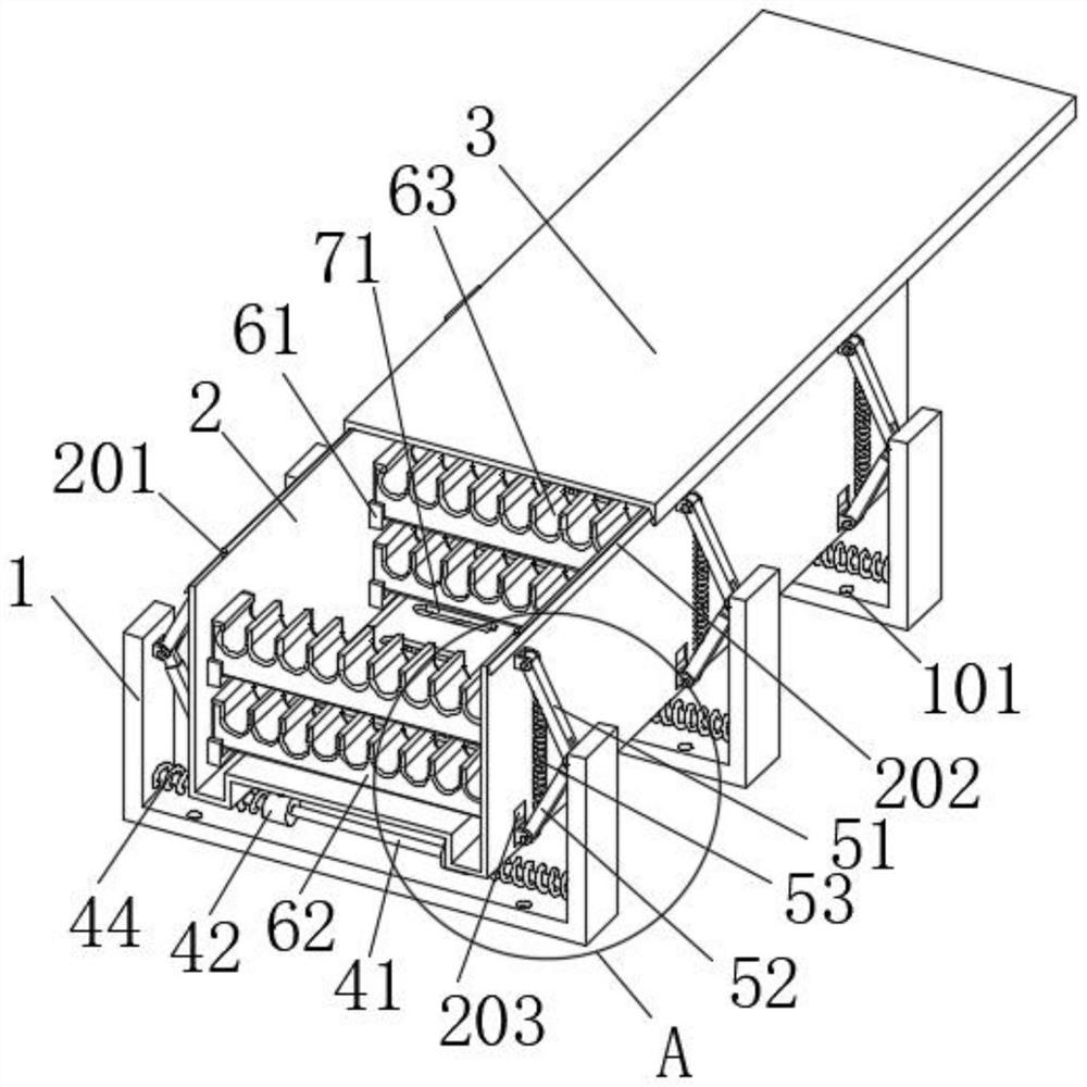
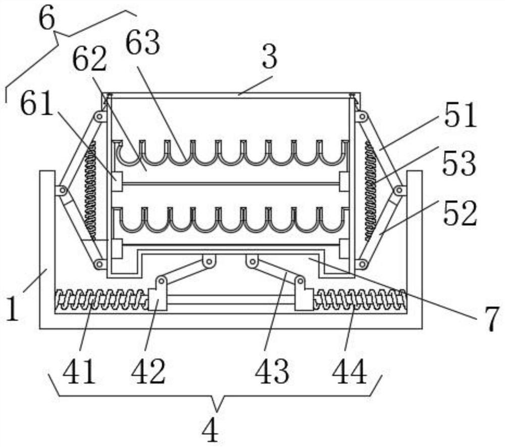
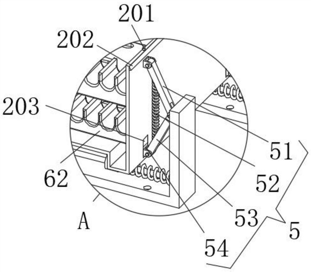
[0028] see Figure 1-4 , the present invention provides a technical solution: an impact-resistant combined cable tray, including a frame body 2, a first buffer assembly 4, a second buffer assembly 5 and a support assembly 6;

[0029] Frame body 2: the bottom plate is provided with an upward rectangular groove 7, and the top plate of the rectangular groove 7 is provided with an array of heat dissipation holes 71. The heat dissipation holes 71 are notch-shaped h...


PUM


Abstract

The invention discloses an impact-resistant combined cable bridge, and the cable bridge comprises a bridge body, a first buffer assembly, a second buffer assembly and a supporting assembly. A bottom plate of the frame body is provided with an upward rectangular groove, and the top end of a side plate of the frame body is connected with an upper cover in a buckled mode. The first buffer assembly isarranged on the lower surface of the frame body in an array mode, and the first buffer assembly comprises a guide rod, a sliding ring, a connecting rod and a first spring, wherein the upper end of the connecting rod is rotationally connected with the interior of a U-shaped connector arranged on the lower surface of the rectangular groove through a pin shaft, and the lower end of the connecting rod is rotationally connected with the interior of the top end of the sliding ring through a pin shaft; The adjacent sliding rings are slidably connected with the outer arc faces of the guide rod, and the ends of the guide rods are fixedly connected with the inner walls of the left side plate and the right side plate of the supporting plate correspondingly. According to the invention, the cable bridge is good in heat dissipation performance, convenient to install and operate, capable of improving the protection performance, capable of conducting buffering protection in the horizontal direction and the vertical direction at the same time, good in impact resistance, long in service life, high in practicability, and wide in application range.

Description

technical field [0001] The invention relates to the technical field of cable bridges, in particular to an impact-resistant combined cable bridge. Background technique [0002] Cable bridges are divided into trough type, tray type, ladder frame type and grid type, etc., which are composed of brackets, brackets and installation accessories. The bridges in buildings can be erected independently or attached to various buildings and pipe gallery brackets. In terms of structure, it should reflect the characteristics of simple structure, beautiful appearance, flexible configuration and convenient maintenance. All parts need to be galvanized. If the bridge frame installed in the open air outside the building is near the sea or belongs to the corrosion area, the material must have Anti-corrosion and moisture-resistant, the combined bridge is the second-generation product of the cable bridge. It is suitable for various projects, various units and various cables. It has the characteris...

Claims


Application Information

Patent Timeline
IPC IPC(8): H02G3/04F16F15/067
CPCF16F15/067H02G3/0412H02G3/0456
Inventor 郭宏富张炳林范韦军
Owner 镇江市神龙电器管件有限公司
Why Eureka
Try Eureka