Supercharge Your Innovation With Domain-Expert AI Agents!

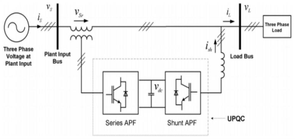
Novel series-parallel system compensation load reactive power demand control method and system

A control method and parallel technology, applied in reactive power compensation, reactive power adjustment/elimination/compensation, AC network circuits, etc. Faults and other issues

Pending Publication Date: 2020-11-10
STATE GRID JIANGSU ELECTRIC POWER CO LIANYUNGANG POWER SUPPLY CO +1
View PDF2 Cites 0 Cited by
  • Summary
  • Abstract
  • Description
  • Claims
  • Application Information

AI Technical Summary

Problems solved by technology

When the reactive power demand of the load is large, the reactive power compensation of the parallel side inverter alone is too large, and the reactive power compensation pressure of the parallel side inverter is too large, which is easy to exceed its rated reactive power capacity, causing inverter failure and affecting system stability.

Method used


Image

  • Novel series-parallel system compensation load reactive power demand control method and system
  • Novel series-parallel system compensation load reactive power demand control method and system
  • Novel series-parallel system compensation load reactive power demand control method and system

Examples


Embodiment

[0162] In order to verify the effectiveness of the solution of the present invention, the following simulation experiments are carried out.

[0163] The power angle control simulation results in the proposed system are shown as Figure 6 As shown, where (a) is the waveform diagram of the power supply voltage, (b) is the waveform diagram of the load voltage, (c) is the waveform diagram of the injection voltage at the series side, (d) is the waveform diagram of the DC voltage, and (e) is the waveform diagram of the power supply current , (f) is the load current waveform diagram, (g) is the parallel compensation current waveform diagram, (h) is the load voltage and power supply voltage waveform diagram.

[0164] From Figures (c) and (g), it can be seen that at t 1 = 0.1s and t 2 =0.2s, the parallel and series inverters are respectively connected to pure resistance loads (15kw); at t 2 to t 3 During this period, due to the existence of resistive loads, the system does not make...


PUM


Abstract

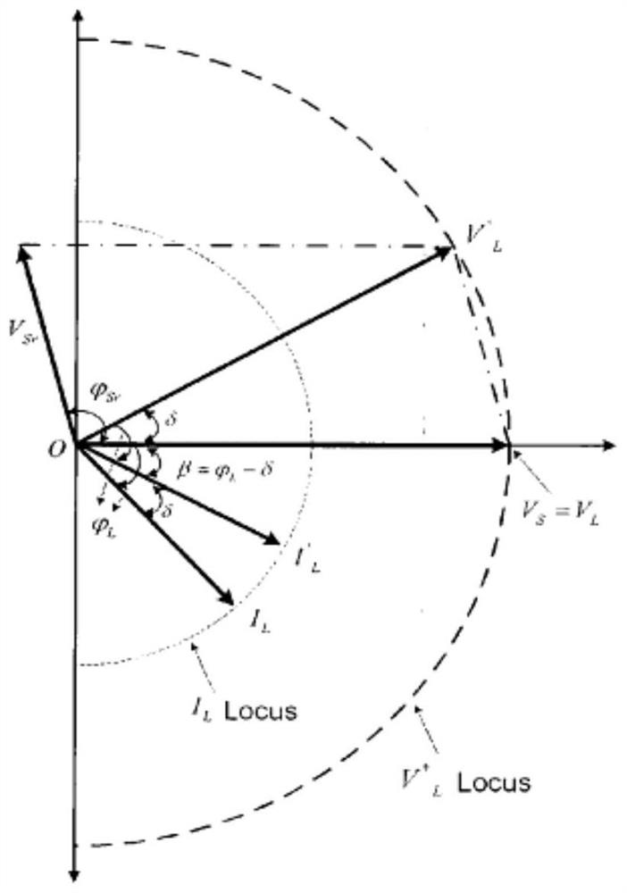
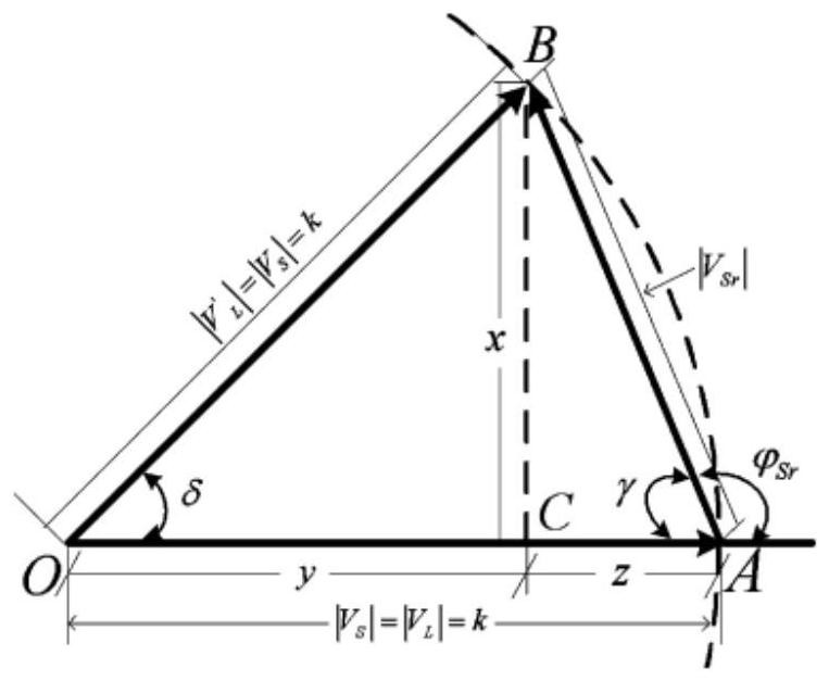
The invention discloses a novel series-parallel system compensation load reactive power demand control method and system, and the method comprises the steps: obtaining a DC component of reactive powerneeded by a load, and determining the reactive power needing to be compensated by a series inverter, i.e., the reactive power vacancy exceeding the rated capacity value of a parallel inverter; calculating a power angle according to the reactive power required to be additionally compensated by the series inverter; generating a three-phase reference voltage signal injected into the series inverteraccording to the power angle; comparing the three-phase reference voltage signal with the actually measured three-phase series injection voltage to generate a switching signal required by switching ofthe series inverter, and controlling the series inverter to compensate the reactive vacancy exceeding the rated capacity value of the parallel inverter. According to the invention, the parallel inverters and the series inverters are controlled to provide load reactive power demands together, so sharing of the load reactive power demands is facilitated, reduction of rated values of the parallel inverters is facilitated, and the total cost of the novel series-parallel system is reduced.

Description

technical field [0001] The invention relates to a novel series-parallel system (UPQC) control method for compensating reactive power demands of loads, and belongs to the field of electric power conversion. Background technique [0002] Power system load reactive power compensation is one of the common problems in power transmission. Parallel capacitor banks are used to compensate load reactive power, which is the simplest load reactive power compensation method, but this method has some disadvantages, such as fixed compensation amount and possible load resonance. The newly researched series-parallel system can be used for load reactive power compensation, in which load reactive power compensation is completed through parallel inverters, while series inverters are usually used to compensate voltage-related problems, not for load reactive power compensation. When the reactive power demand of the load is large, the reactive power compensation of the parallel side inverter alon...

Claims


Application Information

Patent Timeline
Patent Type & Authority Applications(China)
IPC IPC(8): H02J3/18
CPCH02J3/1814Y02E40/30
Inventor 伏祥运郁正纲孙海霞朱立位陈浩李红封波岳付昌
Owner STATE GRID JIANGSU ELECTRIC POWER CO LIANYUNGANG POWER SUPPLY CO
Features
  • R&D
  • Intellectual Property
  • Life Sciences
  • Materials
  • Tech Scout
  • Unparalleled Data Quality
  • Higher Quality Content
  • 60% Fewer Hallucinations
Learn More