Sounding device and electronic equipment with same

A sound-generating device and substrate technology, applied in the directions of sound-generating equipment, electrical components, instruments, etc., can solve problems such as sound leakage, and achieve the effects of avoiding sound leakage, preventing swing, and improving vibration stability.

Active Publication Date: 2020-11-10
AAC TECH NANJING
View PDF7 Cites 4 Cited by
  • Summary
  • Abstract
  • Description
  • Claims
  • Application Information

AI Technical Summary

Problems solved by technology

[0005] The purpose of the present invention is to provide a sounding device and electronic equipment with it, which is used

Method used


Image

  • Sounding device and electronic equipment with same
  • Sounding device and electronic equipment with same
  • Sounding device and electronic equipment with same

Examples


Embodiment 1

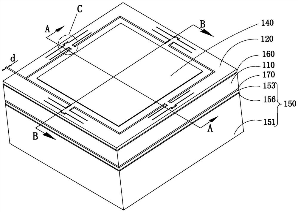
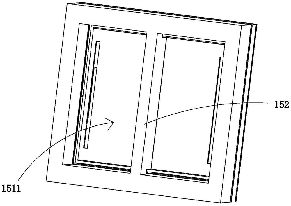
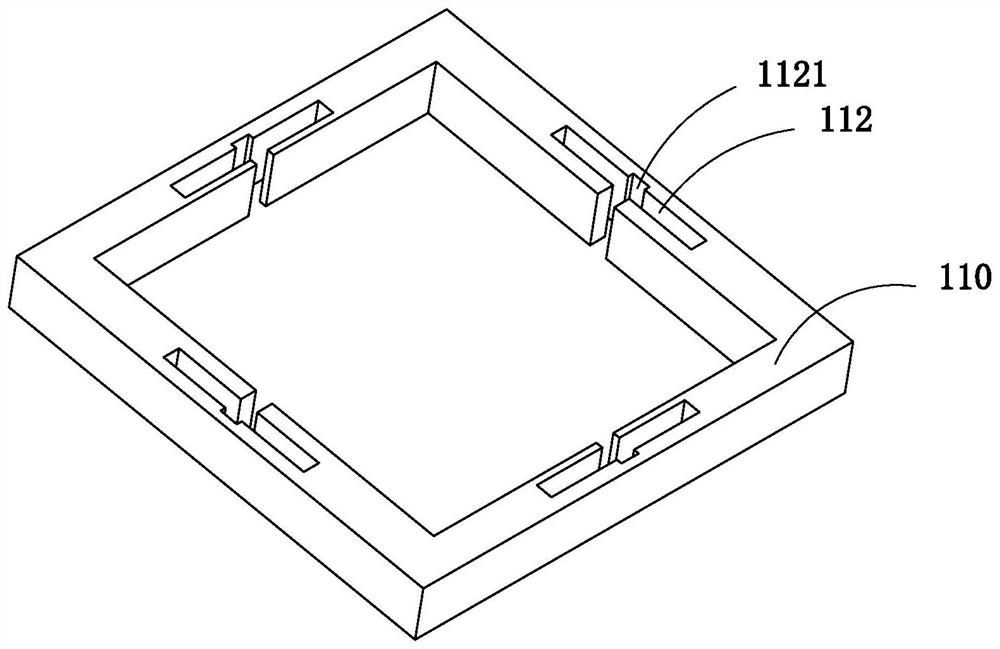
[0033] refer to Figure 1-8 , the present invention discloses a sounding device, comprising a first substrate 110 with a first through hole in the center, a vibrating layer 120 arranged above the first substrate 110, a vibrating layer 120 connected to the vibrating layer located in the first through hole The connecting piece and the driving device for driving the vibrating layer 120 to vibrate. The vibrating layer 120 includes a fixing part 121 located above the first base body 110 and fixed to the first base body 110, a diaphragm 124 suspended above the first through hole, and a connecting diaphragm 124 and the elastic connecting member 123 of the fixing part 121; the elastic connecting member 123 includes a connecting part 1231 for connecting the diaphragm 124 and an elastic part 1232 capable of moving along the central axis direction of the diaphragm 124, and one end of the connecting part 1231 is connected to the diaphragm 124, the other end of the connecting part 1231 is ...

Embodiment 2

[0059] refer to Figure 9 -14, the sound generating device of the second embodiment is adjusted on the basis of the first embodiment. Specifically, the size of the annular connecting member 230 , the structure of the diaphragm 224 covered by the annular connecting member 230 , and the structure of the second driver 250 are adjusted.

[0060] In this embodiment, the cross-sectional size of the annular connecting member 230 is reduced, which is smaller than the size of the diaphragm 224 and also smaller than the cross-sectional size of the third through hole 2511 .

[0061] In order to increase the strength of the diaphragm 2241 extending from the annular connector 230 to the edge of the diaphragm 224, preferably, the thickness of the diaphragm 2241 in this area is increased, and in order to increase the vibration amplitude of the diaphragm above the second through hole 231, preferably, To reduce the thickness of the diaphragm in this part of the region, in order to increase th...

Embodiment 3

[0066] refer to Figure 15 -17. In this embodiment, the annular connector 330 is designed in a circular shape, and the center of the second base 351 is provided with a circular third through hole 3511, and the diameter of the third through hole 3511 is larger than the diameter of the annular connector 330 , the cantilever driving plate 353 fixedly connected with the second base 251 is arranged on the second base 351 symmetrically distributed about the central axis, the number of the cantilever driving plate 353 is at least 2, the free end of the cantilever driving plate 353 is the driving end, and the driving The end is connected with the ring-shaped connecting piece 330, and the driving end drives the ring-shaped connecting piece 330 to move along the direction of the central axis.

[0067] A piezoelectric unit is disposed on each cantilever driving plate 353 , and a fixed end of the piezoelectric unit is disposed on the second base 351 .

[0068] The present invention also ...


PUM


Abstract

The invention provides a sounding device and electronic equipment with the same, and the sounding device comprises a first base body with a first through hole in the center, a vibration layer disposedabove the first base body, a connecting piece which is located in the first through hole and is connected with the vibration layer, and a driving device which drives the vibration layer to vibrate. The vibration layer comprises a fixing part which is positioned above the first base body and is fixed on the first base body, a vibrating diaphragm which is suspended above the first through hole, andan elastic connecting component which is connected with the vibrating diaphragm and the fixing part; the elastic connecting component comprises a connecting part used for connecting the vibrating diaphragm and an elastic part capable of moving along the central axis direction of the vibrating diaphragm, one end of the connecting part is connected with the vibrating diaphragm, the other end of theconnecting part is connected with the elastic part, the elastic part is connected with the fixed part, and the elastic part is located above the first base body; the first base body is provided witha receding groove matching the elastic part. According to the invention, the problems of unstable vibration and insufficient full frequency domain of the vibrating diaphragm in the prior art are effectively solved.

Description

【Technical field】 [0001] The invention relates to the field of electroacoustic conversion, in particular to a sound generating device and electronic equipment with the same. 【Background technique】 [0002] A microspeaker using MEMS (Micro Electro Mechanical System) technology may be electrostatic, electromagnetic, or piezoelectric, and in particular, a piezoelectric microspeaker may operate at a lower voltage than an electrostatic type. In addition, the piezoelectric type microspeaker can have a simple structure and can be made thinner than the electromagnetic type microspeaker. [0003] In order to make the piezoelectric micro-speaker cover a larger frequency range, there is currently a dual-drive MEMS speaker solution, which includes a diaphragm, a driver, a piezoelectric unit connected to the diaphragm, and a connecting rod connecting the driver and the diaphragm. One end of the connecting rod is connected to the center of the diaphragm, and the other end of the connecti...

Claims


Application Information

Patent Timeline
IPC IPC(8): H04R7/04G10K9/122
CPCH04R7/04G10K9/122H04R2400/11
Inventor 但强程诗阳朱国李杨
Owner AAC TECH NANJING
Why Eureka
Try Eureka