Bionic queen bee mailing device
A queen bee and beehive technology, which is applied in the field of bee breeding, can solve problems such as abnormal oviposition of good breeds, disability of queen bees, etc., and achieve the effect of ensuring nutritional needs
Pending Publication Date: 2020-11-13
吉林省养蜂科学研究所
0 Cites 2 Cited by
AI-Extracted Technical Summary
Problems solved by technology
[0004] The purpose of the present invention is to provide a bionic queen bee mailing device to solve the problems in the above-mentioned prior art. The bee species mailed by the device ar...
Method used
The lid 18 of bee-leading cover is opened, and cover body 16 is covered on queen bee and worker bee that needs mailing, can make queen bee and worker bee crawl into along cover body 16 by the phototaxis of honeybee, and draws bee by two Any one of the openings 17 can enter the beehive 1 smoothly. The cover body 16 and the beehive 1 are designed separately. One end of the cover body 16 protrudes and extends out of the beehive 1, so as to avoid unintentional trapping of worker bees or When the queen bee is crushed to death, she can inhabit the two bionic combs after entering the beehive 1. The bionic combs are arranged in parallel and spaced apart, which can satisfy the queen bee and worker bees to inhabit between the two adjacent bionic combs, which is more suitable for the queen bee It is also beneficial for worker bees to secrete royal jelly. At this time, the first baffle plate 4 and the second baffle plate 5 are respectively at the positions of the first skylight 6 and the second window 7 and the first skylight 6 and the second window 7 Cover, the water feeding room is connected with the activity room, the worker bees can enter the water feeding room to drink water at any time, the feed room is connected with the activity room, the worker bees can enter the feed room through the window to eat at any time, when it is necessary to add feed and water, through Lift the first baffle plate 4 and the second baffle plate 5 from the first skylight 6 and the second window 7 by 90 degrees so that they are flush with the first slide plate 26 and the second slide plate 27, and then place the first baffle plate 4, The second baffle plate 5 is pushed down to realize the temporary separation of the...
Abstract
The invention discloses a bionic queen bee mailing device. The device comprises a beehive, an activity chamber, a feed chamber and a water feeding chamber are arranged in the beehive, a bionic honeycomb for queen bees to lay eggs is arranged in the activity chamber, a first partition plate is arranged between the activity chamber and the feed chamber, a second partition plate is arranged between the feed chamber and the water feeding chamber, the first partition plate is perpendicularly and fixedly connected to the second partition plate, a bee leading cover is inserted into one side of the beehive in a penetrating mode, and one end of the bee leading cover extends out of the beehive; a through window is downwards formed in the top end of the first partition plate, a first baffle mechanismis slidably connected into the through window, a second baffle mechanism is slidably connected between the side face of the beehive and the second partition plate, a first through groove is downwardsformed in the top end of the second partition plate and is close to the first partition plate, and a lifting rod mechanism is slidably connected into the first through groove; and the top end of thebeehive is covered with a beehive cover, and a first skylight and a second skylight are formed in the beehive cover. The device solves the problems of abnormal improved variety spawning and queen beedisability caused by queen bee mailing between a breeding field and a beekeeper.
Application Domain
Beehives
Technology Topic
HoneycombBeehive +5
Image
Examples
- Experimental program(1)
Example Embodiment
[0032] The technical solutions in the embodiments of the present invention will be clearly and completely described below in conjunction with the accompanying drawings in the embodiments of the present invention. Obviously, the described embodiments are only a part of the embodiments of the present invention, rather than all the embodiments. Based on the embodiments of the present invention, all other embodiments obtained by those of ordinary skill in the art without creative work shall fall within the protection scope of the present invention.
[0033] In order to make the above objectives, features and advantages of the present invention more obvious and understandable, the present invention will be further described in detail below with reference to the accompanying drawings and specific embodiments.
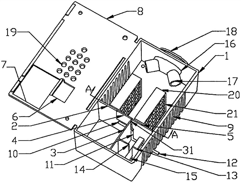
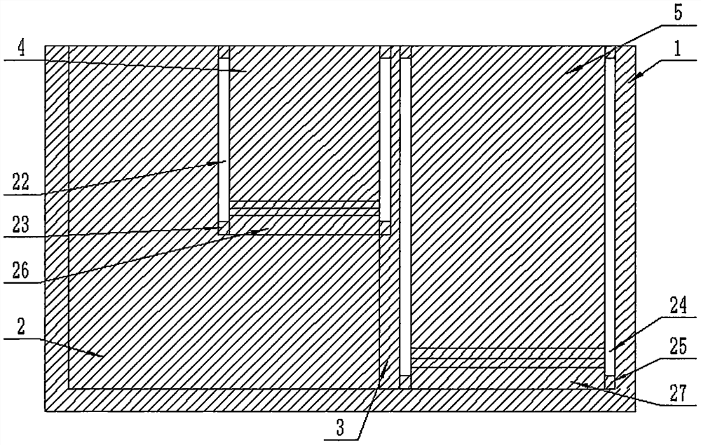
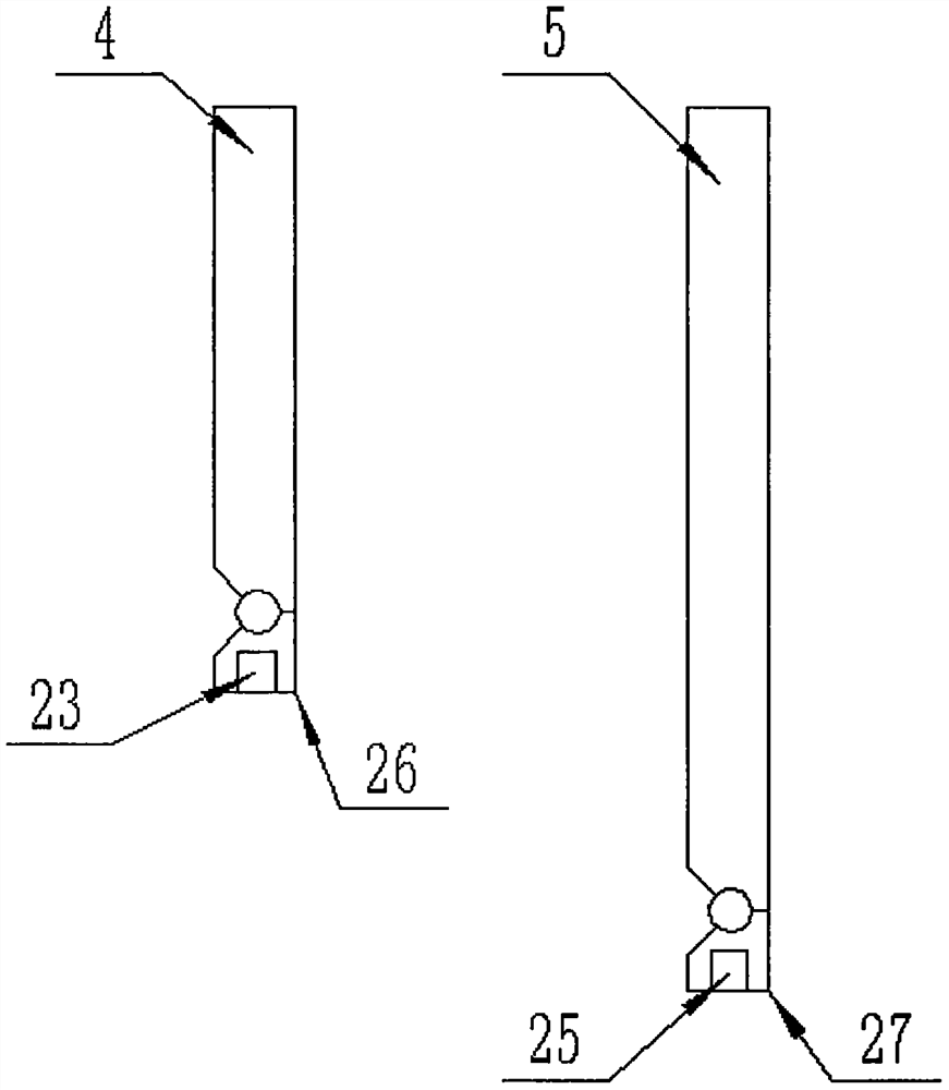
[0034] Reference Figure 1-7 , The present invention provides a bionic queen bee mailing device, which includes a beehive 1. An activity room, a feed room and a water feeding room are arranged in the beehive 1, and a bionic comb spleen for the queen bee to lay eggs is arranged in the activity room. A first partition 2 is provided, and a second partition 3 is provided between the feed room and the water feeding chamber. The first partition 2 and the second partition 3 are vertically fixed, the first partition 2, the second partition 3 And the side of the beehive 1 is enclosed as a feed room, and the second partition 3 and the side of the beehive 1 are enclosed as a water feeding room;
[0035] The side of the beehive 1 away from the feed room is inserted through a bee guide cover, one end of the bee guide cover extends out of the beehive 1, and a number of vents 9 are provided on both sides of the beehive 1 close to the bionic comb spleen;
[0036] A through window is opened at the top of the first partition 2 downward, a first baffle mechanism is slidably connected in the through window, a second baffle mechanism is slidably connected between the side of the beehive 1 and the second partition 3, and the second partition 3 A first through groove 31 is opened at the top end, the first through groove 31 is close to the first partition 2, and a lifting rod mechanism is slidably connected in the first through groove 31;
[0037] The top of the beehive 1 is covered with a beehive cover 8, and the end of the beehive cover 8 away from the bee guide cover is provided with a first skylight 6 and a second skylight 7.
[0038] In a further preferred solution, the number of bionic comb spleens in this embodiment is two, and the two bionic comb spleens are inserted in parallel and spaced apart on the bottom surface of the beehive 1. The bionic comb spleen includes a square base plate 20, and a number of six sides are provided on both sides of the base plate 20 The bottom of the base plate 20 is fixed with a convex block 28, and the bottom surface of the beehive 1 is provided with a concave hole 29, and the convex block 28 matches the concave hole 29.
[0039] In a further preferred solution, the bee guide cover includes a cover body 16, which penetrates the side of the beehive 1, and the end of the cover body 16 extending into the beehive 1 is obliquely and symmetrically fixed with a bee guide port 17, which is connected to the cover body 16. The end of the cover 16 protruding out of the beehive 1 is detachably connected with a cover 18, a rubber strip (not shown in the figure) is connected between the cover 18 and the cover, the cover 18 is fastened on the end of the cover 16, and the cover After 18 is disassembled, it is hung on the cover 16 through a rubber strip. The cover 16 and the beehive 1 are designed separately. One end of the cover 16 protrudes out of the beehive 1 to avoid accidentally pulling the worker bees or queen bees due to the side wall of the beehive 1 when attracting bees. The condition of crushing, and through the phototaxis of the bees, the queen bee and the worker bees can crawl into the mailing beehive 1 through the bee guide cover by themselves, and the two bee guide openings 17 can be set diagonally to make the queen bee and the worker bees crawl in by themselves More smoothly.
[0040] In a further preferred solution, the first baffle mechanism includes a first baffle 4, a first sliding plate 26 is axially connected to the bottom end of the first baffle 4, a first sliding block 23 is symmetrically fixed on both sides of the first sliding plate 26, and two through windows The first sliding groove 22 is symmetrically opened on the side, and the first sliding groove 22 is slidably connected with the first sliding block 23. The width of the through window is equal to the width of the first baffle 4, and the length of the first baffle 4 is the same as that of the first sliding plate 26. The sum of the heights is equal to the height of the window. The first baffle 4 can slide up and down in the first sliding grooves 22 on both sides of the window through the first sliders 23 on both sides of the first slide plate 26 to move the first baffle 4 upwards. When pulling up to the top end, the first sliding block 23 is stuck at the top of the first through slot 31. By rotating the first baffle 4, the first baffle 4 and the first sliding plate 26 are rotated by 90 degrees and buckled in On the first day, the window 6 realizes the communication between the feed room and the activity room, and the worker bees can enter the feed room to eat through the window at any time.
[0041] In a further preferred solution, the second baffle mechanism includes a second baffle 5, a second sliding plate 27 is axially connected to the bottom end of the second baffle 5, and a second sliding block 25 is symmetrically fixed on both sides of the second sliding plate 27. The side of the plate 3 away from the window and the inner wall of the side of the beehive 1 is provided with a second slide groove 24, the second slide groove 24 is slidably connected with the second sliding block 25, the width of the water feeding chamber is equal to the width of the second baffle 5. The sum of the length of the second baffle plate 5 and the height of the second slide plate 27 is equal to the height of the second baffle plate 3, and the second baffle plate 5 can be in the second slide groove 24 through the second sliding block 25 on both sides of the second slide plate 27 Slide up and down to lift the second baffle 5 upwards. When it is lifted to the top end, the second sliding block 25 is stuck on the top of the second through slot 14. By rotating the second baffle 5, the second baffle 5 and the The second slide plate 27 rotates 90 degrees and is buckled on the second skylight 7 to realize the communication between the water feeding room and the activity room, and the worker bees can enter the water feeding room to drink water at any time.
[0042] In a further preferred solution, the first skylight 6 is above the feed room, the second skylight 7 is above the water feeding room, and the side of the first skylight 6 close to the bee guiding hood is flush with the side of the first baffle 4 close to the bee guiding hood. The side of the second skylight 7 close to the bee guide cover is flush with the side of the second baffle 5 close to the bee guide cover. The width of the first skylight 6 is equal to the width of the first baffle 4, and the length of the first skylight 6 is less than that of the first baffle. The length of the plate 4, the width of the second skylight 7 is equal to the width of the second baffle 5, the length of the second skylight 7 is less than the length of the second baffle 5, and the first baffle 4 and the second baffle 5 are pulled up After rising and turning 90 degrees, the first baffle 4 and the second baffle 5 can be placed at the positions of the first skylight 6 and the second skylight 7 respectively, and the first skylight 6 and the second skylight 7 can be covered. The worker bees are eating Or will not flee when drinking water.
[0043] In a further preferred solution, the lifting rod mechanism includes a first connecting rod 10, a second connecting rod 11, and a third connecting rod 12. The first connecting rod 10 and the third connecting rod 12 are arranged in parallel, and the first connecting rod 10 and the third connecting rod The second connecting rod 11 is vertically fixed between 12, the first connecting rod 10 is on the side of the bottom end of the window, the third connecting rod 12 is on the bottom surface of the water feeding chamber, and the first connecting rod 10 is close to the end of the second connecting rod 11. Is inserted into the first through groove 31, the length of the first through groove 31 is equal to the height of the through window, the third connecting rod 12 extends out of the beehive 1 and is inserted into the vent 9 which has a strip-shaped structure. A connecting rod 10 is slidably connected in the first through slot 31, and the third connecting rod 12 is slidably connected in the strip-shaped vent 9. By lifting and lowering the third connecting rod 12, the first connecting rod 10 and the second connecting rod are realized 11. The third link 12 moves up and down synchronously, which can drive away the worker bees or queen bees that may exist in the gap between the feed room, the water feeding room and the activity room, after closing the first baffle 4 and the second baffle 5. There will be no worker bees or queen bees that may exist in the gaps between the feed room, the water feeding room and the activity room.
[0044] In a further preferred solution, a third partition 13 is provided in the water feeding chamber, and the third partition 13 is vertically fixed to the second partition 3, and the third partition 13 is provided with a second through groove 14 in the second through groove 14 The sponge strip 15 is inserted, and the sponge strip 15 is dipped in water and inserted into the second channel 14 to prevent water from being spilled during the mailing process.
[0045] In a further preferred solution, a plurality of vent holes 19 are formed through the beehive cover 8, and four bases 30 are fixedly connected to the bottom surface of the beehive 1.
[0046] The working principle of the bionic queen bee mailing device of the present invention:
[0047] Open the cover 18 of the bee guide cover, and cover the cover body 16 on the queen bee and worker bees that need to be mailed. The phototaxis of the bees can make the queen bee and worker bees crawl in along the cover body 16 and pass through the two bee guide ports 17 Any one of the two can enter the beehive 1 smoothly. The cover 16 and the beehive 1 are designed separately, and one end of the cover 16 protrudes out of the beehive 1 to avoid accidentally crushing the worker bees or queen bees due to the side wall of the beehive 1 when attracting bees When entering the beehive 1, you can inhabit the two bionic spleens. The bionic spleen can be arranged in parallel and spaced apart, which can satisfy the queen and worker bees to inhabit between the two adjacent bionic spleens, which is more suitable for the queen bee to lay eggs. At the same time, it is also beneficial to the worker bees to secrete royal jelly. At this time, the first baffle 4 and the second baffle 5 are respectively at the positions of the first skylight 6 and the second skylight 7 and cover the first skylight 6 and the second skylight 7. The water feeding room is connected with the activity room. The worker bees can enter the water feeding room to drink water at any time. The feed room is connected to the activity room. The worker bees can enter the feed room to eat through the window at any time. The baffle 4 and the second baffle 5 are first lifted 90 degrees from the first skylight 6 and the second skylight 7 to make them flush with the first and second slide plates 26 and 27, and then the first baffle 4 and the second baffle The board 5 is pushed down to realize the temporary separation of the feed room, the water feeding room and the activity room, ensuring that the queen bee and worker bees will not escape the hive 1 when adding feed and water. In addition, before adding feed and water, First, the first link 10 and the third link 12 are reciprocated up and down, which can drive away the worker bees or queen bees that may exist in the gaps in the space between the feed room, the water feeding room and the activity room. After the baffle 5, the worker bees or queen bees that may exist in the gap between the feed room, the water feeding room and the activity room will not be crushed to death; after the feed and water are placed, the first baffle 4 and the second baffle The second baffle 5 is lifted upwards, the first baffle 4 slides up in the first sliding grooves 22 on both sides of the window through the first sliding blocks 23 on both sides of the first sliding plate 26, and the second baffle 5 passes through the second sliding plate. The second sliding blocks 25 on both sides of 27 slide upward in the second sliding groove 24 until they are lifted to the top. By rotating the first baffle 4 and the second baffle 5, the first baffle 4 and the first slide 26 rotate 90 degrees and buckle on the first skylight 6, so that the second baffle 5 and the second slide plate 27 rotate 90 degrees, and buckle on the second skylight 7, to realize the communication between the feed room, the water feeding room and the activity room , The worker bees can continue to enter the feed room to eat and drink through the window at any time.
[0048] In the description of the present invention, it should be understood that the terms "longitudinal", "lateral", "upper", "lower", "front", "rear", "left", "right", "vertical", The orientation or positional relationship indicated by "horizontal", "top", "bottom", "inner", "outer", etc. is based on the orientation or positional relationship shown in the drawings, and is only for the convenience of describing the present invention, rather than indicating or It is implied that the device or element referred to must have a specific orientation, be configured and operated in a specific orientation, and therefore cannot be understood as a limitation of the present invention.
[0049] The above-mentioned embodiments only describe the preferred mode of the present invention, and do not limit the scope of the present invention. Without departing from the design spirit of the present invention, those of ordinary skill in the art have made various contributions to the technical solutions of the present invention. Variations and improvements should fall within the scope of protection determined by the claims of the present invention.
PUM


Description & Claims & Application Information
We can also present the details of the Description, Claims and Application information to help users get a comprehensive understanding of the technical details of the patent, such as background art, summary of invention, brief description of drawings, description of embodiments, and other original content. On the other hand, users can also determine the specific scope of protection of the technology through the list of claims; as well as understand the changes in the life cycle of the technology with the presentation of the patent timeline. Login to view more.