Abdominal cavity washing drainage device

An abdominal cavity and irrigation tube technology, applied in the field of medical devices, can solve problems such as poor suction and bleeding, and achieve the effects of avoiding bleeding, reducing the degree of dispersion, and reducing the amount of water

Inactive Publication Date: 2020-11-13
THE FIRST AFFILIATED HOSPITAL OF MEDICAL COLLEGE OF XIAN JIAOTONG UNIV
View PDF6 Cites 0 Cited by
  • Summary
  • Abstract
  • Description
  • Claims
  • Application Information

AI Technical Summary

Problems solved by technology

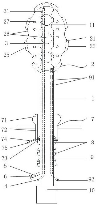
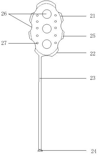
[0004] In order to solve the above-mentioned problems in the prior art, that is, in order to solve the problem of poor suction or even bleeding when the existing three sleeves are used in the densely distributed areas of the intestine and mesentery, the present invention provides a peritoneal irrigation and drainage device, It includes an inner sleeve and a mesh liquid bag; the mesh liquid bag includes an inner layer, an outer layer and a first water inlet pipe, the inner layer is wrapped to form a first hollow structure, and a second layer is formed between the outer layer and the inner layer. Two hollow structures, the first water inlet pipe is provided with an opposite first end and a second end, the first end communicates with the outer layer; the inner layer and the outer layer are provided with a plurality of adjacent A combined connection area, the connection area is provided with a through hole, and the inner sleeve extends into the first hollow structure through one of the through holes; one end of the inner sleeve is closed, and the other end is open, and the inner sleeve is closed. The closed end of the inner sleeve protrudes into the first hollow structure and is fixedly connected with the mesh liquid bag, and the tube wall of the inner sleeve located in the first hollow structure is provided with several first Suction port; a suction tube is placed inside the inner casing, and several second suction ports are arranged on the wall of the suction tube

Method used


Image

  • Abdominal cavity washing drainage device
  • Abdominal cavity washing drainage device

Examples


Embodiment Construction

[0021] Preferred embodiments of the present invention are described below with reference to the accompanying drawings. Those skilled in the art should understand that these embodiments are only used to explain the technical principles of the present invention, and are not intended to limit the protection scope of the present invention.

[0022] It should be noted that, in the description of the present invention, the terms "center", "upper", "lower", "left", "right", "vertical", "horizontal", "inner", "outer" etc. The terms of the indicated direction or positional relationship are based on the direction or positional relationship shown in the drawings, which are only for the convenience of description, and do not indicate or imply that the device or element must have a specific orientation, be constructed and operated in a specific orientation , and therefore cannot be construed as a limitation of the present invention. In addition, the terms "first", "second", and "third" ar...


PUM


Abstract

The invention relates to the field of medical instruments, in particular to an abdominal cavity washing drainage device. The invention aims to solve the problems of unsmooth suction and even bleedingwhen an existing three-way tube is used for an intestinal canal and an area with densely distributed mesenteries. In order to achieve the purpose, the abdominal cavity washing drainage device comprises an inner sleeve and a net-shaped liquid bag. The net-shaped liquid bag comprises an inner layer, an outer layer and a first water inlet pipe, and the inner layer wraps to form a first hollow structure; the inner layer and the outer layer are provided with a plurality of attached connecting areas, the connecting areas are provided with through holes, and the inner sleeve extends into the first hollow structure through one of the through holes; a suction tube is arranged in the inner sleeve, and a plurality of second suction openings are formed in the tube wall of the suction tube. Pressure can be buffered through the surface of the net-shaped liquid bag and the gap between the inner sleeve and the suction tube, and intestinal canal injury and bleeding are effectively avoided.

Description

technical field [0001] The invention relates to the field of medical instruments, in particular to a peritoneal washing and drainage device. Background technique [0002] At present, three casings are mostly used for peritoneal washing clinically. The three sleeves include drainage tube, inner sleeve and irrigation tube. The inner sleeve and irrigation tube are arranged inside the drainage tube; the side wall of the drainage tube is provided with several suction ports, and the inner sleeve sucks away the peritoneal effusion through the suction ports . During the suction process, due to the small size of the drainage tube and the large negative pressure formed by the inner sleeve, for the area where the intestinal tract and mesentery are densely distributed, the abdominal wall of the intestinal tract and mesentery may not be sucked smoothly, and even appear after suction. Injury bleeding. [0003] Correspondingly, a new peritoneal washing and drainage device is needed in t...

Claims


Application Information

Patent Timeline
Patent Type & Authority Applications(China)
IPC IPC(8): A61M1/00A61M3/02A61M25/00A61M25/10
CPCA61M1/0058A61M3/02A61M3/0279A61M3/0283A61M25/0026A61M25/007A61M25/0043A61M25/10A61M25/1002A61M2210/1021A61M1/85A61M1/84
Inventor 刘司南张靖垚曲凯毕文超刘昌
Owner THE FIRST AFFILIATED HOSPITAL OF MEDICAL COLLEGE OF XIAN JIAOTONG UNIV
Why Eureka
Try Eureka