High-concentration stirring tank

A stirring tank, high-concentration technology, which is used in mixer accessories, mixers with rotary stirring devices, mixers, etc., can solve the problems of insufficient stirring, limited mixing effect, and insufficient performance, and achieve thorough and uniform mixing. Effect

Inactive Publication Date: 2020-11-13
CHANGZHOU XINWU MACHINERY
View PDF14 Cites 4 Cited by
  • Summary
  • Abstract
  • Description
  • Claims
  • Application Information

AI Technical Summary

Problems solved by technology

[0004] In the prior art, stirring is generally carried out through a stirring tank or a mixing barrel. After the material is added into the tank, the stirring wheel inside is used for stirring and mixing. The main problem is that the stirring is insufficient. Traditionally, two blades are generally set to The opposite stirring wheel is driven by a drive shaft. The rotation direction of the two stirring wheels is the same. The lower material in the tank is pushed from bottom to top, while the upper material is pushed from top to bottom to complete the mixing. This kind of stirring wheel The layout method will prolong the required mixing time when the initial material is stratified, because the upper layer of material cannot reach the bottom of the tank in one push flow, and some blades are arranged in the same direction of rotation and rotate in the same direction. It is to push the material in one direction, but it only flows in a relatively large height range. It does not fully utilize the characteristics of the two mixing wheels drumming each other and then axially flowing against each other, and the mixing effect is also limited.

Method used


Image

  • High-concentration stirring tank
  • High-concentration stirring tank
  • High-concentration stirring tank

Examples


Embodiment Construction

[0030] The following will clearly and completely describe the technical solutions in the embodiments of the present invention with reference to the accompanying drawings in the embodiments of the present invention. Obviously, the described embodiments are only some, not all, embodiments of the present invention. Based on the embodiments of the present invention, all other embodiments obtained by persons of ordinary skill in the art without making creative efforts belong to the protection scope of the present invention.

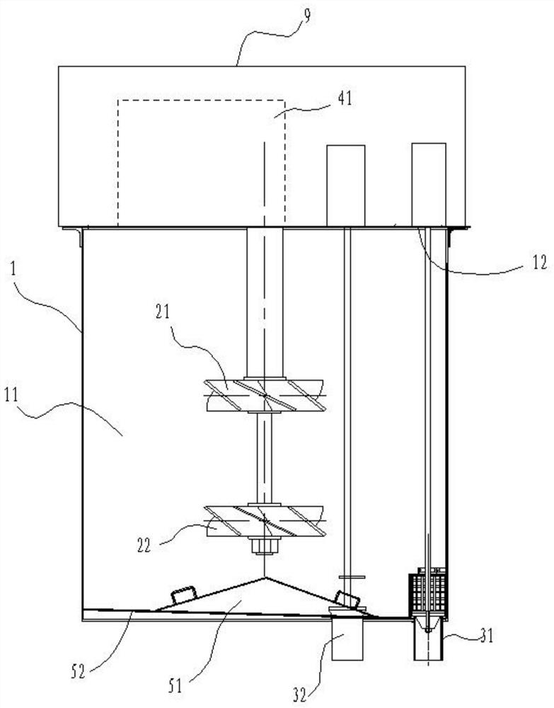
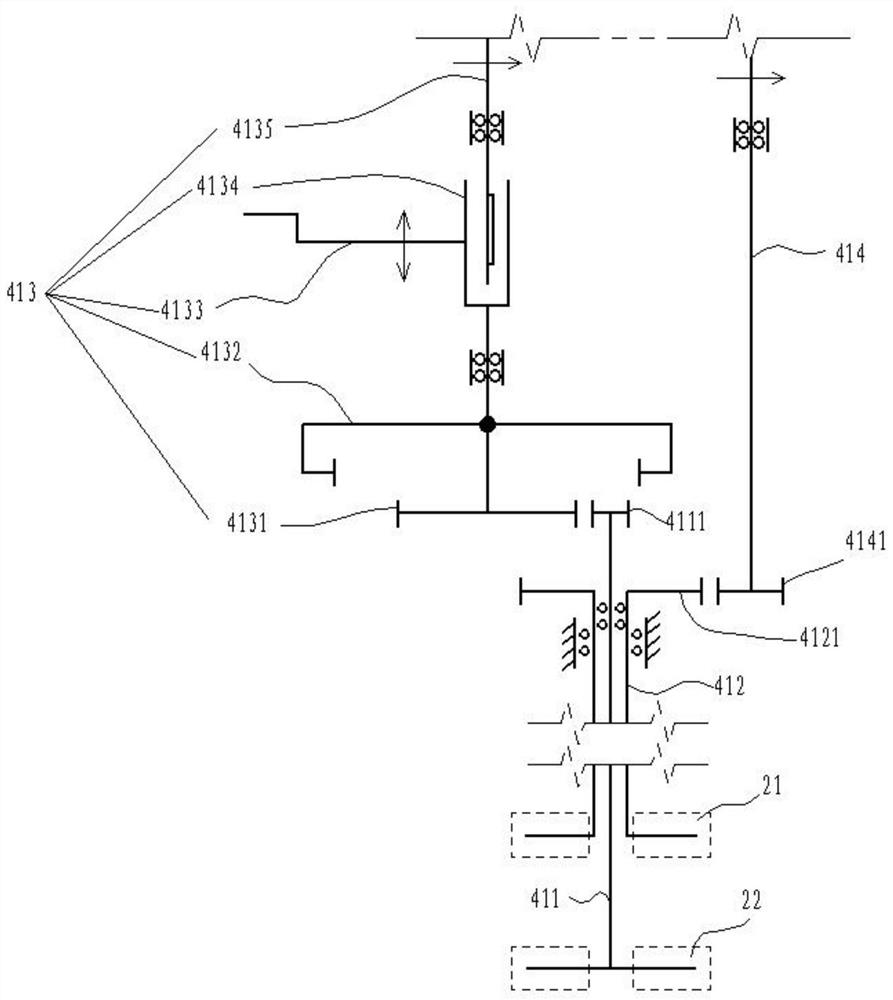
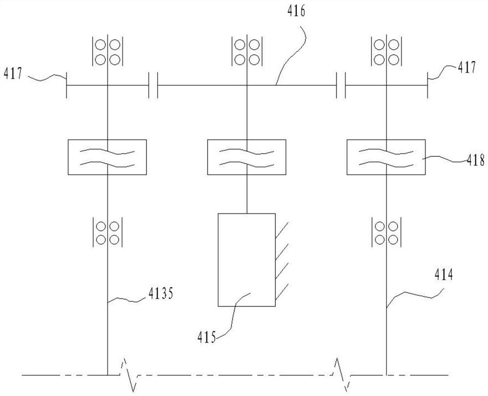
[0031] Such as Figure 1~6 As shown, the high-concentration stirring tank includes a housing 1, a first stirring wheel 21, a second stirring wheel 22, and a drive assembly 41. The inside of the housing 1 is a stirring chamber 11, and the first stirring wheel 21 and the second stirring wheel 22 are all Located in the stirring chamber 11 and coaxially arranged, the driving assembly 41 is arranged on the top of the housing 1, and the driving assembly 41 drives th...


PUM


Abstract

The invention discloses a high-concentration stirring tank. The high-concentration stirring tank comprises a shell, a first stirring wheel, a second stirring wheel and a driving assembly, wherein a stirring cavity is formed in the shell; the first stirring wheel and the second stirring wheel are both located in the stirring cavity and are coaxially arranged; the driving assembly is arranged at thetop of the shell and drives the first stirring wheel and the second stirring wheel to rotate; the first stirring wheel and the second stirring wheel are axial-flow type blade stirring wheels, and therotating directions of blades of the first stirring wheel and the second stirring wheel are the same; a discharging opening is downwards formed in one side of the bottom of the shell; the first stirring wheel and the second stirring wheel are independently driven in a split manner, the rotation direction of the first stirring wheel is to push materials from top to bottom, and the second stirringwheel is located below the first stirring wheel; and the driving assembly comprises a mandrel, a sleeve shaft, a mandrel driver, a second transmission shaft and a motor, the sleeve shaft is hollow, the bottom end of the sleeve shaft is connected with the first stirring wheel, the mandrel penetrates through the sleeve shaft, and the bottom end of the mandrel is connected with the second stirring wheel.

Description

technical field [0001] The invention relates to the field of mixers, in particular to a high-concentration mixing tank. Background technique [0002] After the mine is mined, there will be a goaf area underground. If left unattended, there will be a great potential safety hazard. [0003] The mixer is used to mix various materials to make it into a filling paste with suitable viscosity, and then discharge it to the area to be filled in the mine. The quality of mixing directly determines the quality of filling. [0004] In the prior art, stirring is generally carried out through a stirring tank or a mixing barrel. After the material is added into the tank, the stirring wheel inside is used for stirring and mixing. The main problem is that the stirring is insufficient. Traditionally, two blades are generally set to The opposite stirring wheel is driven by a drive shaft. The rotation direction of the two stirring wheels is the same. The lower material in the tank is pushed fro...

Claims


Application Information

Patent Timeline
Patent Type & Authority Applications(China)
IPC IPC(8): B01F7/18B01F7/00B01F15/00
CPCB01F27/191B01F27/213B01F27/90B01F35/3204B01F35/3214B01F35/332
Inventor 孙泽云
Owner CHANGZHOU XINWU MACHINERY
Why Eureka
Try Eureka