Fixing device for stirring blade welding
A technology of fixing device and stirring blade, applied in welding equipment, auxiliary device, auxiliary welding equipment, etc., can solve the problems of easy injury to people and low welding efficiency.
- Summary
- Abstract
- Description
- Claims
- Application Information
AI Technical Summary
Problems solved by technology
Method used
Image

Examples
Embodiment 1
[0040] A fixing device for stirring blade welding, such as figure 1 As shown, it includes a base 1, a fixing seat 2, a clamping mechanism 3 and an ejection mechanism 4. A fixing seat 2 is provided on the rear side of the base 1, and the clamping mechanism 3 is arranged inside and on the top of the fixing seat 2. There is an ejection mechanism4.
[0041] When it is necessary to weld the stirring blade, first place the blade on the placement part of the clamping mechanism 3, place the steel pipe on the part of the ejection mechanism 4, then hold the part of the clamping mechanism 3 and shake it counterclockwise, clamp The parts placed on both sides of the clamping mechanism 3 drive the blades to move to the middle. When the blades are in close contact with the steel pipe, stop shaking the parts of the clamping mechanism 3, and manually use an electric welding machine to weld the blades. Tightening mechanism 3 unclamps the clamping to blade, then manually pushes up the rear side...
Embodiment 2
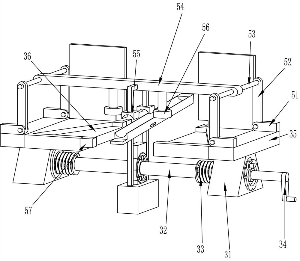
[0043] Overall, such as Figure 1-4 As shown, the clamping mechanism 3 includes a nut 31, a rotating shaft 32, a threaded rod 33, a handle 34 and a blade placement plate 35, and a rotating shaft 32 is rotatably installed on the supporting part of the ejection mechanism 4, and the two ends of the rotating shaft 32 are provided with threaded rods. 33, the right end of the rotating shaft 32 is connected to the handle 34, the threaded rods 33 at the two ends of the rotating shaft 32 have opposite thread directions, the threaded rods 33 at both ends are provided with nuts 31, the tops of the nuts 31 on both sides are connected to the blade placement plate 35, and the blade placement plate 35 All have placement groove 36.
[0044] Put the blade on the blade placement plate 35, put the steel pipe on the parts of the ejection mechanism 4, manually shake the handle 34 counterclockwise, the rotating shaft 32 will rotate accordingly, and the nuts 31 at both ends of the rotating shaft 32 ...
Embodiment 3
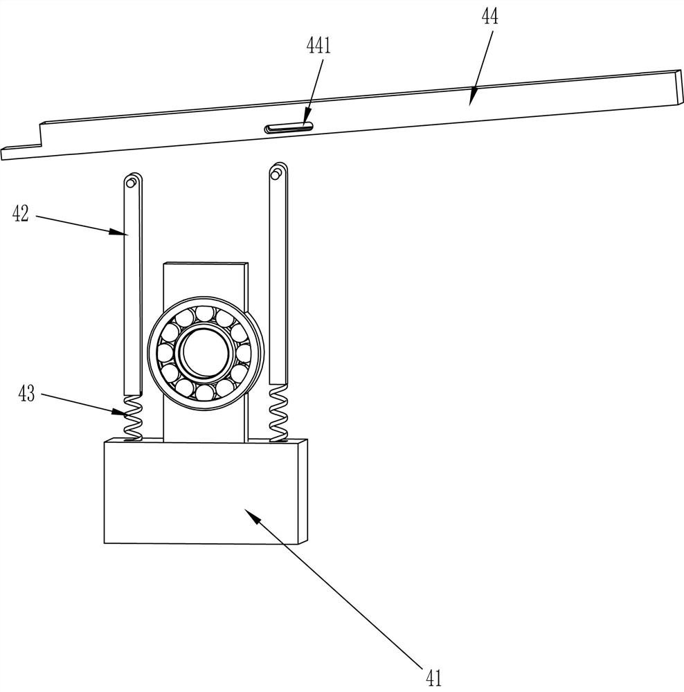
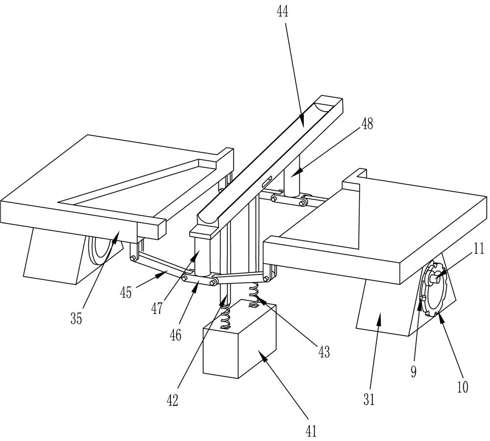
[0048] Specifically, such as Figure 1-3 Shown, also comprise the 3rd rotating bar 45, support plate 46, small support block 47 and large support block 48, the left front and rear two ends of left side blade placement plate 35 and the left side front and rear two ends of right side blade placement plate 35 The third rotating rod 45 is installed on the end, and the third rotating rod 45 ends on both sides are connected to the support plate 46 in a rotating manner. The top of the supporting plate 46 on the front side is equipped with a small support block 47, and the support on the rear side A large support block 48 is installed on the top of the plate 46, and both the small support block 47 and the large support block 48 can be in contact with the bottom of the arc placed plate 44.
[0049]The arc-shaped placement plate 44 is in an inclined state before welding work is performed. When performing welding work, the blades are first placed on the blade placement plate 35, and the...
PUM
 Abstract
Description
Claims
Application Information
 - R&D
- Intellectual Property
- Life Sciences
- Materials
- Tech Scout
- Unparalleled Data Quality
- Higher Quality Content
- 60% Fewer Hallucinations
Browse by: Latest US Patents, China's latest patents, Technical Efficacy Thesaurus, Application Domain, Technology Topic, Popular Technical Reports.
© 2025 PatSnap. All rights reserved.Legal|Privacy policy|Modern Slavery Act Transparency Statement|Sitemap|About US| Contact US: help@patsnap.com