Workpiece fixing device for vertical machining center

A fixed device, vertical technology, used in positioning devices, metal processing mechanical parts, metal processing and other directions, can solve the problem of unable to lock, unable to reduce the buffer of the device, etc., to eliminate the damage of the device, ensure the fixation, and avoid manual operation. Effect

Active Publication Date: 2020-11-13
常德市金艺机械制造有限公司
View PDF5 Cites 4 Cited by
  • Summary
  • Abstract
  • Description
  • Claims
  • Application Information

AI Technical Summary

Problems solved by technology

[0003] At present, the fixing device of the vertical machining center cannot be locked when fixing the workpiece, and the buffer for the device cannot be reduced while fixing

Method used


Image

  • Workpiece fixing device for vertical machining center
  • Workpiece fixing device for vertical machining center
  • Workpiece fixing device for vertical machining center

Examples


Embodiment 1

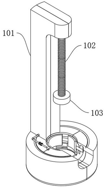
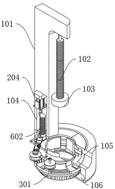
[0029] refer to Figure 1-6 , a workpiece fixing device for a vertical machining center, comprising: a vertical machining frame 101, an elastic hydraulic tube 102 and an adsorption probe 103, the upper end of the vertical machining frame 101 is fixedly connected to the upper end of the elastic hydraulic tube 102, and the lower end of the elastic hydraulic tube 102 is connected to the upper end of the elastic hydraulic tube 102 The axis of the upper surface of the adsorption probe 103 is fixedly connected;

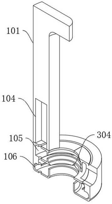
[0030] The vertical processing frame 101 is provided with a starting chamber 104, a locking inflatable chamber 105 and a mobile fixed chamber 106 in sequence from top to bottom. The upper end of the starting chamber 104 is fixedly installed with a driving mechanism, and the inner part of the starting chamber 104 is equipped with a pneumatic buffer fixing mechanism. Locking inflatable bin 105 is equipped with locking inflatable mechanism, and mobile fixed bin 106 is fixedly ...

Embodiment 2

[0032] Embodiment 2: the difference based on Embodiment 1 is;

[0033] Drive mechanism comprises: rotating gear 201, rotating wheel 202, rotating wheel group 203, servomotor 204 and rotating screw mandrel 205, and servomotor 204 main shaft is sequentially connected with rotating screw mandrel 205, rotating wheel group 203, rotating wheel 202, The rotating wheel set 203 is fixedly connected with the rotating gear 201, the rotating screw mandrel 205 is threadedly connected with the pneumatic buffer fixing mechanism, the rotating gear 201 is meshed with the mobile fixing mechanism, the rotating wheel 202 is flexibly connected with the locking inflation mechanism, and the rotating wheel set 203 is connected with the locking inflation mechanism. Mechanism fixed connection.

[0034] The fixing mechanism includes: a rotating gear ring 301 and a moving block 302. The rotating gear ring 201 is meshed with the rotating gear ring 301. The rotating gear ring 301 is movably installed insid...

Embodiment 3

[0039] Embodiment 3: based on Embodiment 1 and 2, but different again is;

[0040] The pneumatic buffering and fixing mechanism includes: compression moving block 601, compression air bag 602, Unicom hose 603 and regulating valve 604, the compression moving block 601 is movably socketed on the rotating screw rod 205, the lower surface of the other side of the compression moving block 601 and the compression air bag The upper end of 602 is fixedly connected, the lower end of the compressed airbag 602 is fixedly connected with the inner wall of the starting chamber 104, the lower end of the compressed airbag 602 is fixedly connected with the upper surface of the rotating ring 401 through the connecting hose 603, the inside of the rotating ring 401 is in a hollow state, and the connecting hose 603 is fixed A regulating valve 604 is installed.

[0041] During use, the rotating wheel 202 and the rotating screw mandrel 205 are driven to rotate synchronously by starting the servo mot...


PUM


Abstract

The invention discloses a workpiece fixing device for a vertical machining center, and belongs to the field of mechanical vertical machining devices. In the using process of the workpiece fixing device, the bottom is adopted for fixing, the upper portion is adopted for adsorption lifting, the device is moved, a small mechanical device is placed in the shaft centre below a vertical machining frame,and then an adsorption probe is loosened; the adsorption probe is recovered through an elastic hydraulic pipe, then a driving mechanism is started to drive a pneumatic buffer fixing mechanism, a locking inflation mechanism and a movable fixing mechanism to operate, and the pneumatic buffer fixing mechanism inflates protective gas into the locking inflation mechanism, so that the locking inflationmechanism expands while locking the device; compression on the device is reduced. In addition, the movable fixing mechanism at the bottom can help the locking inflation mechanism to better adapt to devices of different sizes, and therefore fixing and subsequent machining of the device are guaranteed.

Description

technical field [0001] The invention relates to the field of mechanical vertical processing devices, in particular to a workpiece fixing device for a vertical processing center. Background technique [0002] The vertical machining center refers to the machining center with the axis of the main shaft and the workbench arranged vertically. It is mainly suitable for processing complex parts such as plates, discs, molds and small shells. The vertical machining center can complete the processes of milling, boring, drilling, tapping and thread cutting, among which the workpiece fixing device is an important component of the vertical machining center. [0003] At present, the fixing device of the vertical machining center cannot be locked when fixing the workpiece, and the buffer for the device cannot be reduced while fixing. Contents of the invention [0004] In order to solve the above problems, the present invention proposes a workpiece fixing device for a vertical machining ...

Claims


Application Information

Patent Timeline
Patent Type & Authority Applications(China)
IPC IPC(8): B23Q3/08B23Q7/00
CPCB23Q3/08B23Q7/00
Inventor 林明青
Owner 常德市金艺机械制造有限公司
Why Eureka
Try Eureka