Plastic recycling device

A technology of plastic recycling and equipment, applied in the field of plastics, can solve problems such as inability to separate plastics and metals

Inactive Publication Date: 2020-11-13
李晓娟
View PDF0 Cites 2 Cited by
  • Summary
  • Abstract
  • Description
  • Claims
  • Application Information

AI Technical Summary

Problems solved by technology

[0002] A lot of large pieces of plastic waste will be produced in the current construction project. These plastic waste will be mixed with other m

Method used


Image

  • Plastic recycling device
  • Plastic recycling device
  • Plastic recycling device

Examples


specific Embodiment approach 1

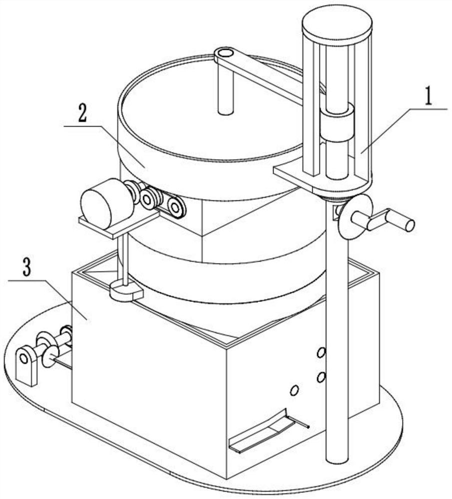
[0027] Combine below Figure 1-12 Describe this embodiment, a kind of plastic recycling equipment, including opening assembly 1, grinding assembly 2 and separation assembly 3, characterized in that: the opening assembly 1 is connected with grinding assembly 2, grinding The crushed assembly 2 is connected with the separation assembly 3, and the separation assembly 3 is connected with the opening assembly 1.

specific Embodiment approach 2

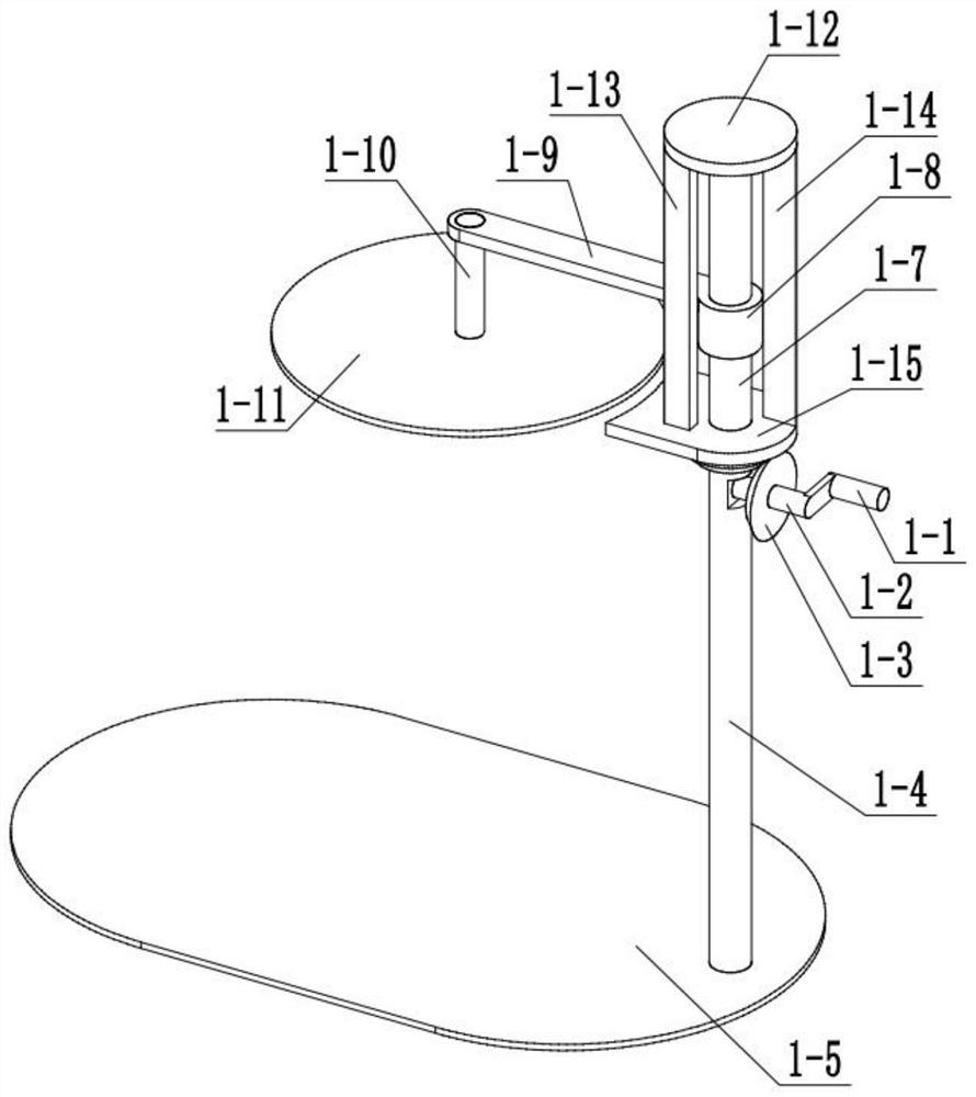
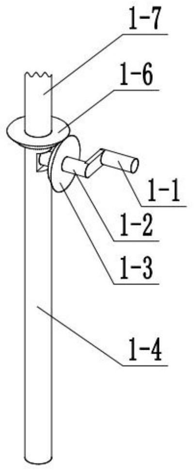
[0029] Combine below Figure 1-12Describe this embodiment, this embodiment will further explain the first embodiment, the cover opening assembly 1 includes a handle 1-1, a handle shaft 1-2, a bevel gear I1-3, a support rod 1-4, and a bottom plate 1-5 , bevel gear Ⅱ1-6, threaded shaft 1-7, threaded sleeve 1-8, rotating rod 1-9, connecting rod 1-10, upper cover 1-11, disc 1-12, limit baffle Ⅰ1- 13. Limit baffle Ⅱ 1-14 and baffle bracket 1-15, handle 1-1 is connected with handle shaft 1-2, handle shaft 1-2 is connected with bevel gear Ⅰ 1-3, handle shaft 1-2 is connected with The support rod 1-4 is rotationally connected, the support rod 1-4 is connected with the bottom plate 1-5, the bevel gear Ⅰ1-3 is meshed with the bevel gear Ⅱ1-6, the bevel gear Ⅱ1-6 is connected with the threaded shaft 1-7, and the thread The shaft 1-7 is rotationally connected with the support rod 1-4, the threaded shaft 1-7 is threaded with the threaded sleeve 1-8, the threaded sleeve 1-8 is connected wi...

specific Embodiment approach 3

[0031] Combine below Figure 1-12 Describe this embodiment mode. This embodiment mode will further explain Embodiment 1. According to claim 1, a kind of plastic recycling equipment is characterized in that: the grinding assembly 2 includes a hopper 2-1, a motor I 2-2, Motor bracket 2-3, cutting box 2-4, grinding box 2-5, fixed connecting plate 2-6, motor I shaft 2-7, bevel gear III 2-8, gear I 2-9, gear II 2-10, Gear Ⅱ shaft 2-11, pulley Ⅰ 2-12, belt Ⅰ 2-13, pulley Ⅱ 2-14, roller shaft 2-15, bevel gear Ⅳ 2-16, bevel gear Ⅳ shaft 2-17, sprocket protection box 2 -18, sprocket Ⅰ 2-19, chain 2-20, sprocket Ⅱ 2-21, milling disc shaft 2-22, milling disc 2-23, rolling bottom plate 2-24, discharge hole 2-25, shredding roller 2 -26 and chopping knife 2-27, baffle bracket 1-15 is connected with hopper 2-1, hopper 2-1 is connected with cutting box 2-4, motor I 2-2 is connected with motor bracket 2-3 , the motor support 2-3 is connected with the cutting box 2-4, the cutting box 2-4 is c...


PUM


Abstract

The invention relates to the field of plastic, and particularly relates to a plastic recycling device. In existing constructional engineering, a lot of large plastic garbage can be generated, the plastic garbage can be doped with other metal, a very large recycling value is achieved, and a traditional device cannot completely separate plastic and metal. The device solves the above problems, a handle is rotated, an upper cover automatically rotates after being lifted, the handle is reversely rotated, the upper cover automatically buckles a hopper after rotating, cover opening and closing are conveniently completed, plastic is added, a chopping knife relatively reversely rotating cuts the large plastic into small blocks, the small plastic blocks are ground by a grinding disc to be discharged, subsequent separation work is facilitated, the ground plastic falls on a conveying magnetic belt under the gravity effect, metal is attracted by the conveying magnetic belt and scraped down by a scraper to be separated from the plastic, and plastic powder and the small plastic blocks are separated through plastic screening of a screening plate.

Description

technical field [0001] The invention relates to a field of plastics, in particular to a plastic recycling device. Background technique [0002] There will be a lot of large pieces of plastic waste in the current construction project, which will be mixed with other metals, which has great recycling value. Traditional equipment cannot completely separate plastic and metal. This equipment solves the above problems. Contents of the invention [0003] The purpose of the present invention is to provide a plastic recycling equipment, which can cut and grind large pieces of plastic, and can separate plastic from metal. [0004] The purpose of the present invention is achieved through the following technical solutions: [0005] A plastic recycling device, comprising an opening assembly, a grinding assembly and a separation assembly, characterized in that: the opening assembly is connected to the grinding assembly, and the grinding assembly is connected to the separation assembly, ...

Claims


Application Information

Patent Timeline
IPC IPC(8): B29B17/04B29B17/02
CPCB29B17/02B29B17/04B29B2017/0203B29B2017/0224B29B2017/0272B29B2017/0476B29B2017/0484Y02W30/52Y02W30/62
Inventor 李晓娟
Owner 李晓娟
Why Eureka
Try Eureka