Supercharge Your Innovation With Domain-Expert AI Agents!

High-speed removing system

A high-speed, rejecting device technology, applied in the field of visual inspection, can solve problems such as inability to accurately reject products and secondary damage to products, and achieve the effect of avoiding inability to accurately reject defective products

Pending Publication Date: 2020-11-13
SSUZHOU ZFUNG AUTOMATION TECH
View PDF6 Cites 0 Cited by
  • Summary
  • Abstract
  • Description
  • Claims
  • Application Information

AI Technical Summary

Problems solved by technology

It solves the problem that the existing rejecting device cannot accurately reject the product, and at the same time easily causes secondary damage to the product

Method used


Image

  • High-speed removing system
  • High-speed removing system
  • High-speed removing system

Examples


Embodiment

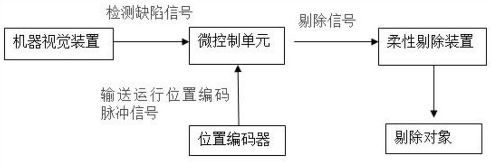
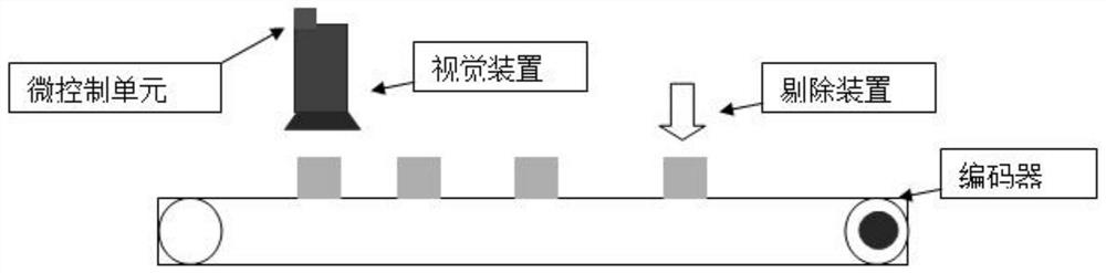
[0024] A high-speed rejecting system, comprising a control box with a micro-control unit inside, a conveying line connected to the control box, a position encoder, a visual device, a rejecting device, and a defective product storage box used in conjunction with the rejecting device, wherein the The control box is connected with the industrial computer, the position encoder is installed on the shaft of the conveying line, the vision device is installed directly above the conveying line, and the rejecting device is installed on the conveying line and at the rear of the vision device.

[0025] In this embodiment, the visual device includes a visual inspection box, and an industrial camera, an industrial lens, and a visual light source are arranged in the visual inspection box, and the visual light source includes a coaxial light source, a dome light source, and a ring light source.

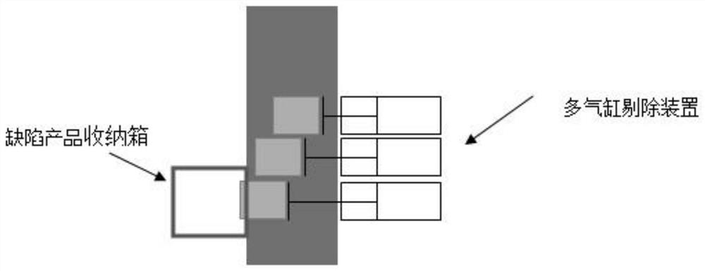
[0026] In this embodiment, the rejecting device includes a cylinder box connected to the conveying...


PUM


Abstract

The invention provides a high-speed removing system. The high-speed removing system comprises a micro-control unit, a machine vision device connected with the micro-control unit and a multi-air-cylinder removing device. The system is segmentally controlled through multiple air cylinders, high-speed grading removing is achieved, and thus the problem that defective products cannot be accurately removed through single removal or the defective products are likely to be secondarily damaged is avoided.

Description

technical field [0001] The invention relates to the technical field of visual inspection, in particular to a high-speed rejection system. Background technique [0002] In the alcoholic beverage industry, it is necessary to carry out online real-time detection of each link in the production and packaging of alcoholic beverages, and to perform high-speed online flexible online elimination of defective alcoholic beverage products. [0003] Existing rejecting systems generally use single-execution cylinders, or rejecting devices in the form of rubber wheel buffers. However, the action of a single cylinder is single, and the one-time operation of the cylinder pushes the object to be removed. The force control is not easy to adjust. If the force is too small, the object cannot be removed, and if the force is too large, the object to be removed will be easily damaged. Contents of the invention [0004] In view of the above-mentioned shortcomings of the prior art, the purpose of ...

Claims


Application Information

Patent Timeline
IPC IPC(8): B65B57/00B65G43/08B65G47/82
CPCB65B57/00B65G43/08B65G47/82B65G2203/041
Inventor 元云飞祝希
Owner SSUZHOU ZFUNG AUTOMATION TECH
Features
  • R&D
  • Intellectual Property
  • Life Sciences
  • Materials
  • Tech Scout
  • Unparalleled Data Quality
  • Higher Quality Content
  • 60% Fewer Hallucinations
Learn More