
Lifting winch for emergency recovery operation of manned submersible

A technology for manned submersibles and emergency recovery, applied to portable lifting devices, clockwork mechanisms, components with teeth, etc., can solve problems such as resource waste, component failure, system power loss, etc., and reduce waiting time , reduce shock and vibration, and reduce the effect of learning difficulty

Active Publication Date: 2020-11-13
SHANGHAI MARINE EQUIP RES INST
View PDF7 Cites 0 Cited by
  • Summary
  • Abstract
  • Description
  • Claims
  • Application Information

AI Technical Summary

Problems solved by technology

[0003] Due to the large weight and shape of the manned submersible, it often operates in harsh sea conditions. The comprehensive influence of wind, waves and currents during the recovery process makes the submersible and the working mother ship have relatively large relative movements. At this time, the submersible is in the process of leaving the sea surface Cables tend to be subject to high shock loads, leading to the possibility of failure of the hoisting winch
In addition, problems such as system power failure, oil leakage, and component failures may occur during the operation. At this time, emergency recovery of the manned submersible must be implemented
[0004] In the prior art, in order to carry out emergency recovery to the manned submersible when the hoisting winch breaks down, a set of emergency recovery device is usually provided separately. limited space; when in use, temporary assembly is required, which not only reduces the emergency recovery efficiency of the manned submersible, but also causes a waste of existing resources

Method used


Image

  • Lifting winch for emergency recovery operation of manned submersible
  • Lifting winch for emergency recovery operation of manned submersible
  • Lifting winch for emergency recovery operation of manned submersible

Examples


Embodiment Construction

[0023] In order to better understand the above-mentioned purpose, features and advantages of the present application, the present application will be further described in detail below in conjunction with the accompanying drawings and specific embodiments. It should be noted that, in the case of no conflict, the embodiments of the present application and the features in the embodiments can be combined with each other.

[0024] In the following description, a lot of specific details are set forth in order to fully understand the application, however, the application can also be implemented in other ways different from those described here, therefore, the protection scope of the application is not limited by the following disclosure Limitations of specific embodiments.

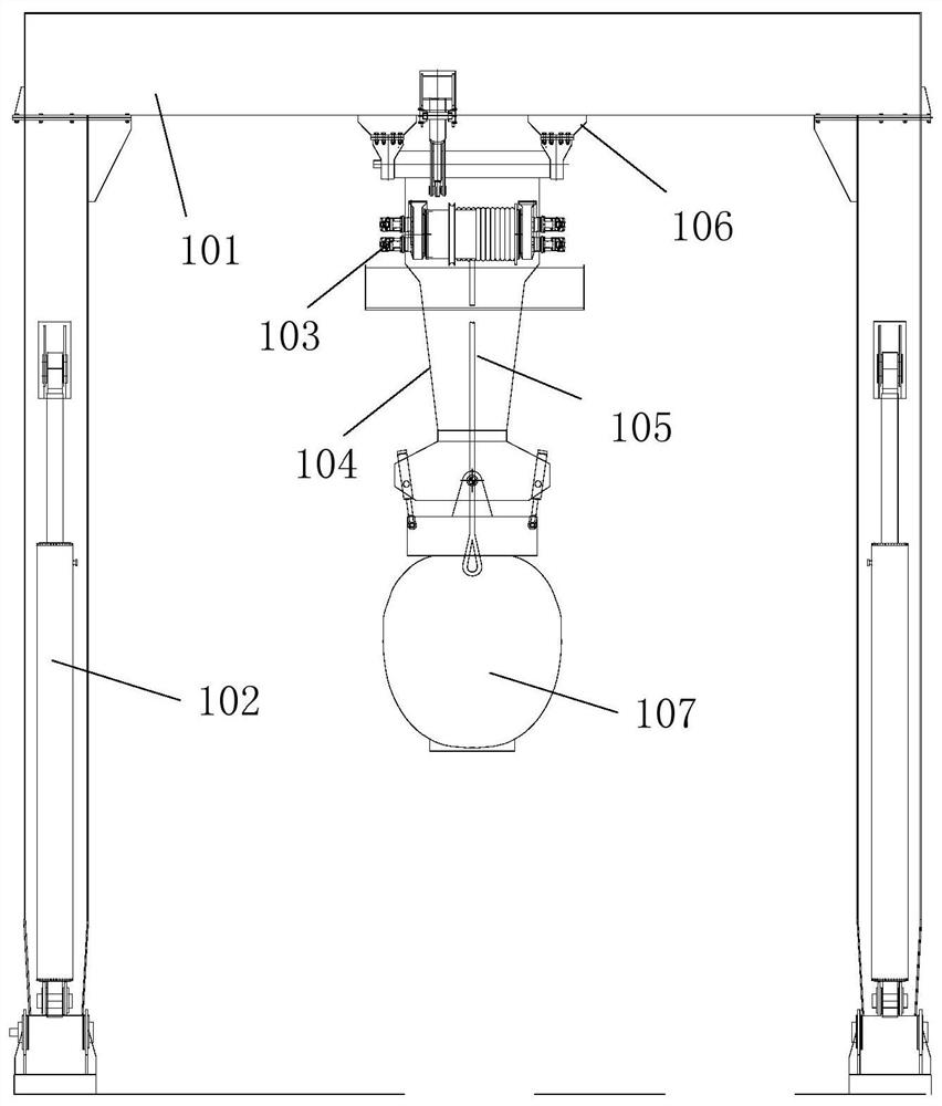
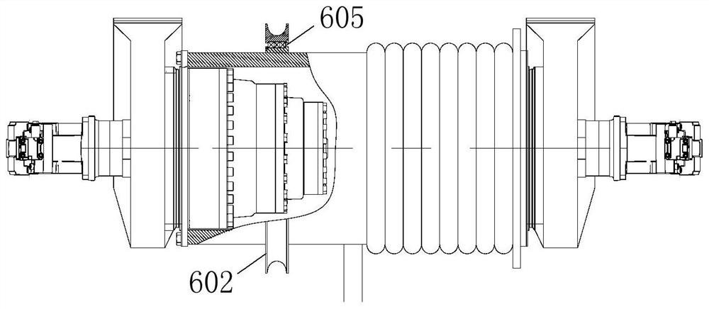
[0025] Such as figure 1 As shown, this embodiment provides a hoisting winch for emergency recovery operations of manned submersibles, the hoisting winch includes a hoisting winch assembly 103, a speed reducer 10...


PUM


Abstract

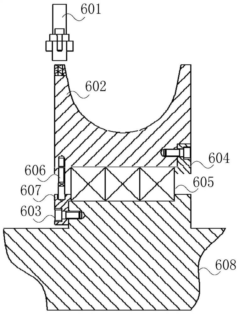
The invention discloses a lifting winch for emergency recovery operation of a manned submersible. The lifting winch comprises a lifting winch assembly and a hydraulic motor. The lifting winch assemblyis characterized in that an annular boss is arranged on a reel, a first bearing cover plate is mounted on the left side of the annular boss, and blind holes are formed above the first bearing cover plate; multiple thin-wall bearings are arranged side by side, the bearing inner rings of the thin-wall bearings are mounted above the annular boss, the bearing outer rings of the thin-wall bearings aremounted below a pulley, and the connection mode between the bearing inner rings of the thin-wall bearings and the annular bosses is a single-side shaft shoulder positioning mode; threaded long holesare formed in the left side of the pulley, set screws are mounted in the threaded long holes, and after the set screws are unscrewed from the blind holes, the pulley can rotate on the reel; and a second bearing cover plate is mounted on the right side of the pulley to limit the thin-wall bearings. By means of the technical scheme, the pulley for emergency recovery is integrally arranged on the reel of an existing lifting winch, and the emergency recovery safety and efficiency of the submersible are improved.

Description

technical field [0001] The present application relates to the technical field of diving equipment, in particular, to a hoisting winch used for emergency recovery operations of manned submersibles. Background technique [0002] Deep-sea science is one of the important directions of the frontier of science, and deep-sea scientific research relies on technical means and equipment support. The manned submersible is a particularly important deep-diving operation equipment. When the manned submersible is operating, a special hoisting system is required to use the lifting winch to deploy the submersible from the deck to the water surface or recover it from the water surface to the deck of the mother ship. [0003] Due to the large weight and shape of the manned submersible, it often operates in harsh sea conditions. The comprehensive influence of wind, waves and currents during the recovery process makes the submersible and the working mother ship have relatively large relative mov...

Claims


Application Information

Patent Timeline
Patent Type & Authority Applications(China)
IPC IPC(8): B66D1/60B66D1/08B66D1/30B66D1/44B66D3/04B66D1/50F15B1/02F15B11/16
CPCB66D1/60B66D1/08B66D1/30B66D1/44B66D3/04B66D1/50F15B1/02F15B11/16
Inventor 丁鑫吴华强刘刚陶俊张涛
Owner SHANGHAI MARINE EQUIP RES INST
Learn More