Aerator for sewage treatment and treatment method thereof

A technology for sewage treatment and aerator, which is applied in water/sewage treatment, biological water/sewage treatment, water/sewage multi-stage treatment, etc. Comprehensive aeration, improve the effect of aeration effect

Inactive Publication Date: 2020-11-13
辽宁鑫知界科技有限公司
View PDF5 Cites 2 Cited by
  • Summary
  • Abstract
  • Description
  • Claims
  • Application Information

AI Technical Summary

Problems solved by technology

[0004] The purpose of the present invention is to solve the problem of low aeration efficiency caused by the low reaction rate of air bubbles and sewage in the prior art, and propose an aerator for sewage treatment and its treatment method

Method used


Image

  • Aerator for sewage treatment and treatment method thereof
  • Aerator for sewage treatment and treatment method thereof
  • Aerator for sewage treatment and treatment method thereof

Examples


Embodiment 1

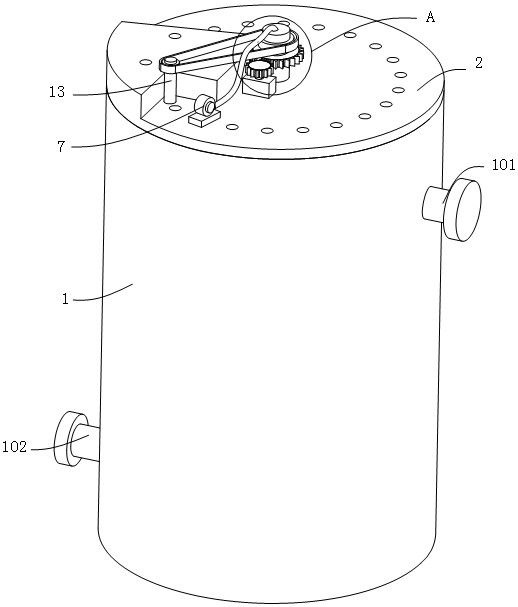
[0039] refer to figure 1 , figure 2 , image 3 and Figure 7 , an aerator for sewage treatment, comprising a body 1 and a machine cover 2, the machine cover 2 is connected to the top of the body 1, the two sides of the outer wall of the body 1 are respectively connected with a water inlet pipe 101 and a water outlet pipe 102, the machine The top of the cover 2 is connected with a motor 3, the output end of the motor 3 is connected with a rotating shaft, the end of the rotating shaft away from the motor 3 is connected with a first gear 301, and the outer wall of the first gear 301 is meshed with a second gear 4, and the center of the cover 2 Rotationally connected with a rotating shaft 5, the second gear 4 is connected to the outer wall of the rotating shaft 5, the outer wall of the rotating shaft 5 is connected with an aeration mechanism, the outer wall of the rotating shaft 5 is connected with a first bevel gear 501, and the outer wall of the first bevel gear 501 is meshed...

Embodiment 2

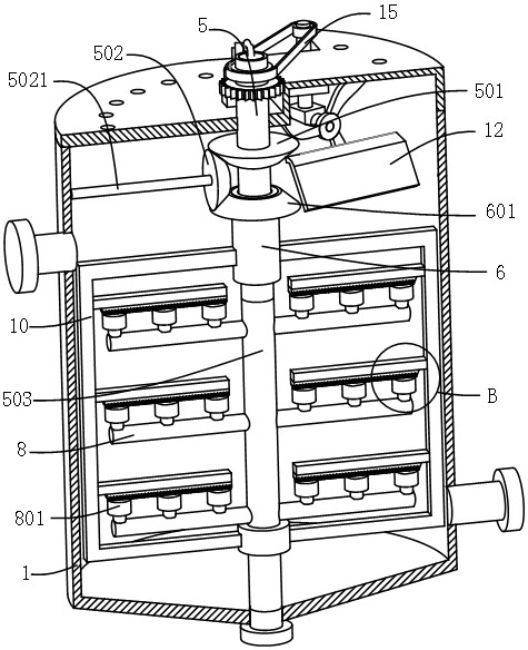
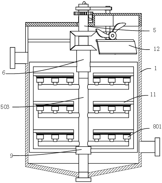
[0042] refer to Figure 1-4 , an aerator for sewage treatment, which is basically the same as that of Embodiment 1, furthermore, the aeration mechanism includes a blower 7, the blower 7 is connected to the outer wall of the machine cover 2, and the air outlet end of the blower 7 is connected with an exhaust Pipe 701, the end of the exhaust pipe 701 away from the blower 7 is connected to the rotating shaft 5, the rotating shaft 5 is set as a hollow pipe, the bottom of the rotating shaft 5 is connected to the main air pipe 503, and the end of the main air pipe 503 away from the rotating shaft 5 is connected to the fuselage 1, the outer wall of the main air pipe 503 is connected with the air distribution pipe 8, the air distribution pipe 8 communicates with the main air pipe 503, the outer wall of the air distribution pipe 8 is connected with an aeration element 801, and the stirring mechanism includes a fixed ring 9 and two fixed frames 10, two Two fixed mounts 10 are respective...

Embodiment 3

[0045] refer to figure 1 , figure 2 , image 3 , Figure 4 , Figure 5 , Figure 7 , an aerator for sewage treatment, which is basically the same as Embodiment 1, furthermore, the inner wall of the fuselage 1 is connected with a deflector 12, and the inside of the cover 2 is connected with a rotating rod 13, and the rotating rod 13 is connected to the The outer wall of the rotating shaft 5 is connected with a matching synchronous wheel 14, and a synchronous belt 15 is connected between the two synchronous wheels 14. The outer wall of the rotating rod 13 is connected with a box body 16, and the box body 16 is fixedly connected to the inner wall of the fuselage 1 through a connecting plate. , the bottom of the rotating rod 13 is connected with the fourth bevel gear 131, the outer wall of the fourth bevel gear 131 is meshed with the fifth bevel gear 17, the fourth bevel gear 131 and the fifth bevel gear 17 are all rotatably connected in the box body 16, the second The outer...


PUM


Abstract

The invention provides an aerator for sewage treatment and a treatment method thereof, and belongs to the technical field of sewage treatment. The aerator for sewage treatment comprises a machine bodyand a machine cover, the cover is connected to the top of the body; two sides of the outer wall of the body are connected with a water inlet pipe and a water outlet pipe; the top of the cover is connected with a motor; the output end of the motor is connected with a rotating shaft; one end of the rotating shaft away from the motor is connected with a first gear; the outer wall of the first gear is engaged with a second gear; a rotation shaft is rotatably connected to the center of the machine cover, a second gear is connected to the outer wall of the rotating shaft, an aeration mechanism is connected to the outer wall of the rotation shaft, a first bevel gear is connected to the outer wall of the rotating shaft, a second bevel gear is meshed with the outer wall of the first bevel gear, and a fixing rod is connected to the outer wall of the second bevel gear and fixedly connected to the inner wall of the machine body; bubbles are smashed and stirred through the stirring mechanism so that sewage and the bubbles are mixed more uniformly, and the aeration efficiency and the aeration effect are improved.

Description

technical field [0001] The invention relates to the technical field of sewage treatment, in particular to an aerator for sewage treatment and a treatment method thereof. Background technique [0002] The random discharge of sewage will have a great negative impact on the environment. At present, people often use aeration tanks to treat sewage. The aeration tank is a structure that uses activated sludge method for sewage treatment. The system and the water inlet and outlet are composed of three parts. The pool body is generally made of reinforced concrete, and the plane shape is rectangular, square, and circular. Aeration is a means of making air and water come into strong contact. Oxygen dissolves in water. [0003] The Chinese patent with the patent number CN201510508005.X in the prior art discloses a small aerator for sewage treatment, including a fuselage, water inlet pipe, water outlet pipe and aeration device, and the whole of the fuselage is a revolving body structur...

Claims


Application Information

Patent Timeline
Patent Type & Authority Applications(China)
IPC IPC(8): C02F3/12C02F7/00C02F9/14
CPCC02F3/12C02F7/00C02F9/00C02F1/001C02F1/283C02F2203/006C02F2303/14Y02W10/10
Inventor 董永欣吕连婷
Owner 辽宁鑫知界科技有限公司
Why Eureka
Try Eureka