Pavement residue cleaning device for road maintenance

A technology for cleaning devices and residues, used in road cleaning, cleaning methods, construction, etc., can solve the problems of slow residues, dust easily scattered everywhere, etc., and achieve the effect of preventing floating everywhere.

Inactive Publication Date: 2020-11-13
徐亚卿
View PDF5 Cites 9 Cited by
  • Summary
  • Abstract
  • Description
  • Claims
  • Application Information

AI Technical Summary

Problems solved by technology

[0005] In order to overcome the disadvantages of slow manual cleaning of residues and easy scattering of dust, the technical problem to be solved by the present invention is to provide a road surface residue cleaning device for road maintenance with fast cleaning speed and capable of reducing dust

Method used


Image

  • Pavement residue cleaning device for road maintenance
  • Pavement residue cleaning device for road maintenance
  • Pavement residue cleaning device for road maintenance

Examples


Embodiment 1

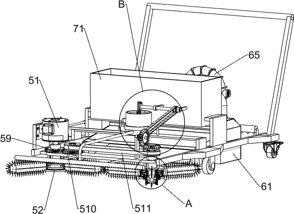
[0023] A road surface residue cleaning device for road maintenance, such as Figure 1-5 As shown, it includes a mounting frame 1, wheels 2, universal wheels 3, a hand push rod 4, a cleaning mechanism 5 and a collecting mechanism 6. Two wheels 2 are connected to the bottom of the mounting frame 1, and the two wheels 2 are left and right symmetrical. The wheels 2 The mounting frame 1 bottom of the rear is connected with universal wheel 3, and the rear side of mounting frame 1 top is connected with push rod 4, and sweeping mechanism 5 and collection mechanism 6 are respectively installed on mounting frame 1.

[0024] The cleaning mechanism 5 includes a servo motor 51, a rotating toothed disc 52, a fixed toothed disc 53, a brush tube 54, a coupling gear 55, a limit ring 56, a fixed rod 57, a fixed plate 58, a first gear 59, a second gear 510 and The first drive belt set 511, the left side of the mounting frame 1 front portion is equipped with a servo motor 51, the fixed plate 58 i...

Embodiment 2

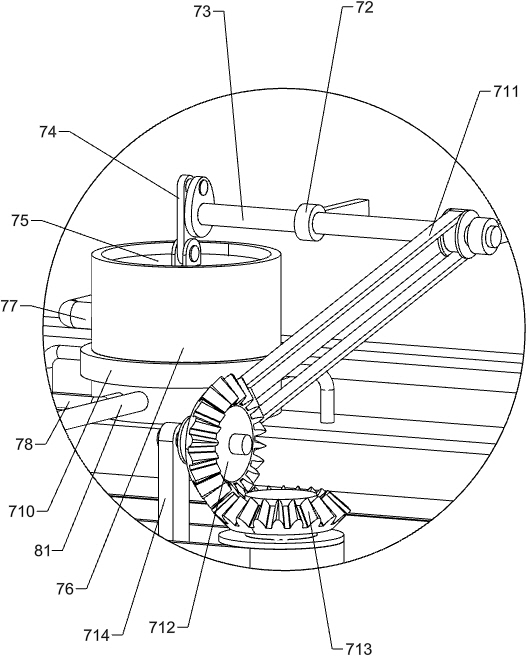
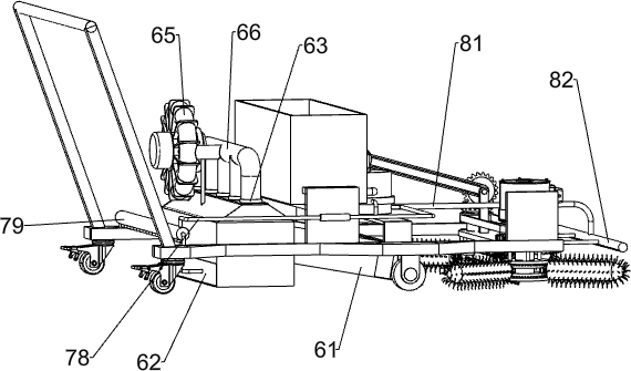
[0028] On the basis of Example 1, such as Figure 1-3 and Figure 6As shown, a flushing mechanism 7 is also included, and the flushing mechanism 7 includes a water tank 71, a fixed ring sleeve 72, a rotating shaft 73, a connecting rod 74, a pressurizing piston 75, a pressurizing barrel 76, a one-way water inlet pipe 77, a first one-way Outlet pipe 78, water spray pipe 79, fixed frame 710, second transmission belt group 711, first bevel gear 712, second bevel gear 713 and fixed block 714, the mounting frame 1 on the front side of suction barrel 61 is connected with water tank 71, two fixed rings 72 are connected to the front side of the water tank 71, and a rotating shaft 73 is rotatably connected between the two fixed rings 72. Rod 74, the mounting frame 1 top of water tank 71 front sides is connected with fixed frame 710, is connected with pressurized bucket 76 on the fixed frame 710, is connected with pressurized piston 75 slidingly in the pressurized bucket 76, and pressur...

Embodiment 3

[0031] On the basis of Example 2, such as figure 1 , image 3 and Figure 6 As shown, a dust suppression structure 8 is also included. The dust suppression structure 8 includes a second one-way water outlet pipe 81 and an atomizing nozzle pipe 82. The pressurized barrel 76 is connected with a second one-way water outlet pipe 81, and the second one-way water outlet pipe The front end of 81 is connected with an atomizing nozzle pipe 82 .

[0032] The downward movement of the pressurizing piston 75 can push the water in the pressurized barrel 76 into the atomizing nozzle pipe 82 through the second one-way water outlet pipe 81, and the water in the atomizing nozzle pipe 82 is sprayed on the road surface thereupon, so that Dust reduction is carried out to prevent the dust from flying around when the road surface is cleaned.


PUM


Abstract

The invention relates to a residue cleaning device, in particular to a pavement residue cleaning device for road maintenance. The technical problem to be solved by the invention is to provide the pavement residue cleaning device for road maintenance, which is high in cleaning speed and can reduce dust. In order to solve the technical problem, the invention provides a pavement residue cleaning device for road maintenance. The device comprises a mounting frame of which the bottom is connected with two wheels, universal wheels, and a sweeping mechanism. The side, away from the wheels, of the bottom of the mounting frame is connected with the universal wheels; and a hand-push rod is connected to one side of the top of the mounting frame. The sweeping mechanism is mounted on the mounting frame.The sweeping mechanism can rapidly sweep residues on the pavement and sweep the residues on the pavement e into a collecting mechanism, the collecting mechanism can collect the residues on the pavement, and a dust falling structure can spray water to the pavement which is not swept yet, so that dust falling can be conducted, and dust is prevented from raising everywhere.

Description

technical field [0001] The invention relates to a residue cleaning device, in particular to a road surface residue cleaning device for road maintenance. Background technique [0002] At present, the cleaning of road residues is generally carried out manually. When manually cleaning the residues, the residues on the road surface are swept into the dustpan one by one with a broom. In this way, the labor intensity of the workers is relatively high, and the cleaning speed is relatively slow, and the When the road surface residues are cleaned, the dust on the road surface is easily swept by the broom, so that the dust is easy to float around, so that the dust easily enters the eyes of pedestrians, thereby affecting the walking of pedestrians. [0003] Therefore urgently need to develop a kind of clearing speed fast, the highway maintenance road surface residue cleaning device that can reduce dust. Contents of the invention [0004] (1) Technical problems to be solved [0005]...

Claims


Application Information

Patent Timeline
Patent Type & Authority Applications(China)
IPC IPC(8): E01H1/08E01H1/10
CPCE01H1/0854E01H1/101
Inventor 徐亚卿
Owner 徐亚卿
Why Eureka
Try Eureka